
AGV AMR Drive Gearbox Calculator
Size an AGV AMR drive gearbox for straight uphill travel. Estimate torque per driven wheel and ratio, then check the missing load cases before selecting.
AGV Wheel Torque Calculator
Live results update immediately on this device. All inputs are required.
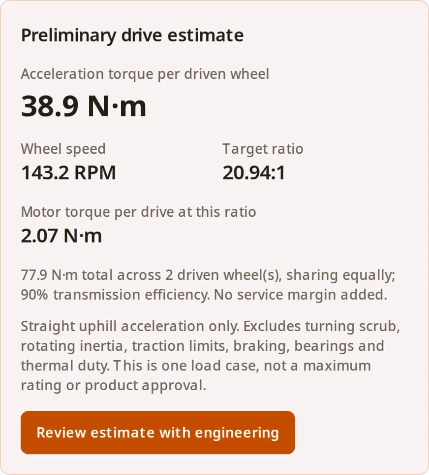
Preliminary drive estimate
- Acceleration torque per driven wheel
- 38.9 N·m
- Wheel speed
- 143.2 RPM
- Target ratio
- 20.94:1
- Motor torque per drive at this ratio
- 2.07 N·m
77.9 N·m total across 2 driven wheel(s), sharing equally; 90% transmission efficiency. No service margin added.
Straight uphill acceleration only. Excludes turning scrub, rotating inertia, traction limits, braking, bearings and thermal duty. This is one load case, not a maximum rating or product approval.
Review estimate with engineeringKey configuration takeaways
Efficiency Target
Compare efficiency at the actual load and speed. A full-load catalogue figure cannot predict an entire vehicle duty cycle.[4]
Load Capacity
Check output bearing loads at the actual wheel offset. A purpose-built wheel drive is one option; an externally supported wheel is another. [3]
Torque Sizing
Check acceleration and continuous duty separately. The tool provides one acceleration case; it does not establish RMS or emergency-stop ratings. [2]
How the estimate is calculated
This is a first-principles translational force balance for constant acceleration from rest, straight uphill travel and equal drive sharing. It is a preliminary model, not a reproduction of a supplier sizing program. Supplier tools also check inertia and RMS duty. [2]
On small screens, scroll tables horizontally to read every column.
| Output | Equation | Meaning |
|---|---|---|
| Acceleration | a = v / t | v: target m/s; t: acceleration seconds |
| Total traction demand | F = m·a + m·g·sin(θ) + Crr·m·g·cos(θ) | m: total kg; θ: slope in degrees converted to radians; Crr: rolling coefficient |
| Wheel torque | Ttotal = F·D/2; Twheel = Ttotal/N | D: diameter in metres (mm / 1000); N: driven wheels sharing equally |
| Speed and ratio | nwheel = 60·v/(π·D); i = nmotor/nwheel | RPM and motor:wheel ratio; a value below 1 means speed increase |
| Motor torque per drive | Tmotor = Twheel/(i·η) | η: transmission efficiency as a fraction; no service margin included |
Three cases you can reproduce
Illustrative calculations, not measured performance: 500 kg, 1.5 m/s, 2 s acceleration, 200 mm wheels, two drives, 3,000 motor RPM and 90% transmission efficiency. Each row uses the equations above; wheel speed is 143.2 RPM and target ratio is 20.94:1.
| Scenario / changed inputs | Total force (N) | Per-wheel torque (N·m) | Motor torque per drive (N·m) |
|---|---|---|---|
| Level floor: θ = 0°, Crr = 0.03 | 522.2 | 26.1 | 1.39 |
| Uphill default: θ = 3°, Crr = 0.03 | 778.7 | 38.9 | 2.07 |
| Higher rolling loss: θ = 3°, Crr = 0.06 | 925.6 | 46.3 | 2.46 |
Decision: measure rolling resistance and test the loaded ramp case before choosing torque ratings. These estimates exclude rotating inertia and do not validate grip or the worst operating load.
Safety & braking: a separate verification task
As reviewed on 2026-09-27, the ISO catalogue lists ISO 3691-4:2023 for driverless industrial trucks and their systems, including AGVs and AMRs. The 2020 edition is withdrawn and a revision is in development. [1]
The public abstract does not substantiate universal scanner delays, docking speeds or a mandatory motor-brake layout. Determine applicable requirements from the full standard and the system risk assessment. Verify stopping and power-off holding under the relevant loaded, sloped and fault conditions. Gearbox torque or apparent self-locking alone does not establish a validated safety function.
Efficiency, heat and battery trade-offs
Treat catalogue efficiency as operating-point data. The NGV wheel-drive catalogue specifies ≥95% at full load for that family. [3] SEW explains why starting conditions, ratio, speed and temperature change losses. [4]
| Decision | Known evidence or method | Required before selection |
|---|---|---|
| Planetary efficiency | NGV example: ≥95% at full load, ratio dependent | Candidate-specific efficiency at the planned load and speed |
| Worm or helical-worm option | Sliding losses; starting and running efficiency differ | Actual product thermal and efficiency data; no universal duty restriction |
| Gearbox heat | Ploss = Pout·(1/η − 1) | Duty-cycle output power, ambient temperature and enclosure heat path |
| Battery runtime | Gear loss is one part of total electrical demand | Motor/drive losses, auxiliaries, battery capacity and mission profile; no range claim available |
Illustrative comparison at 500 W mechanical output: assumed η = 0.95 gives 26.3 W gearbox loss; assumed η = 0.70 gives 214.3 W. These are hypothetical efficiencies, not class ratings or measured battery savings. Validate temperature over the full mission.
AGV wheel gearbox and AMR wheel drive layouts
Mobile robot drivetrains typically fall into three categories. The choice affects packaging volume, ground clearance, and maintenance.
| Architecture | Pros | Cons | Typical Application |
|---|---|---|---|
| In-Wheel Drive (Hub Motor/Gear) | Can free chassis space by placing drive components inside the wheel. | Check heat rejection, wheel-bearing shock loads and access for service. | Low-profile AMRs, tight warehouse logistics. |
| Right-Angle Drive (Bevel-Planetary) | Motor mounts parallel to chassis side, saving longitudinal space. | Extra stage and mounting interfaces; obtain the complete drive efficiency map. | Heavy-duty AGVs, tuggers with narrow track widths. |
| Inline Planetary (Offset Wheel) | A separate motor and inline reducer can simplify component replacement. | Motor protrudes perpendicularly into the chassis space. | Large industrial AGVs, outdoor mobile platforms. |
Selection risks and practical alternatives
The following are engineering review prompts for this simplified model. Actual acceptance limits remain project and supplier specific.
| Risk | Consequence | Mitigation / alternative |
|---|---|---|
| Misuse: one acceleration case treated as maximum torque | Turning, thresholds or stops can demand more | Collect all load cases and permitted cycle counts; review cyclic and emergency limits separately |
| Scenario mismatch: unequal wheel loading or grip | Equal torque division does not ensure usable traction | Check traction with actual wheel normal loads; model worst-loaded drive or revise suspension |
| Thermal overload inside the chassis | Motor or gearbox cannot sustain the mission | Check motor RMS duty and supplier gearbox thermal method; improve heat path or reduce duty |
| Wheel offset and impact loads | Output bearing or shaft overload | Use rated radial/axial/moment data at the offset; use external wheel bearings if needed |
| Cost: unnecessarily tight backlash or oversizing | Higher purchase cost, mass and packaging demand | Set a reversal-error budget and test docking; compare complete installed and service cost |
| Stopping or downhill regeneration omitted | Braking and electrical energy paths remain unverified | Review stop loads, holding and driver/battery energy absorption with the system designer |
What is known before an RFQ?
| Item | Current status | Next evidence |
|---|---|---|
| Acceleration force, wheel speed, theoretical ratio | Calculated from your inputs under stated assumptions | Confirm the input measurements and catalogue ratio |
| Motor capability | Unknown: no motor curve or supply voltage entered | Torque-speed curve at minimum battery voltage and controller current limit |
| Continuous and cyclic gearbox duty | Unknown: no full mission entered | Load/time history, cycle count, thermal limit and life calculation |
| Bearing and traction capacity | Unknown: geometry and adhesion not entered | Wheel offset, normal loads, floor tests and output-bearing limits |
| Safety and stopping performance | Not evaluated by this calculator | Applicable requirements and loaded-vehicle validation records |
For an example of voltage and ramp effects on a specific motor/driver family, see [5]. Product features do not establish system compliance.
Methodology and Data Sources
Published by Robotized Gearbox (Magatom Dynamics Co., Ltd.). The equations and worked cases are our preliminary calculations. Rolling resistance 0.03 and efficiency 90% are editable example assumptions, not measured vehicle data. The references below support the stated selection considerations within their listed scopes.
- [1] ISO 3691-4:2023 — Driverless industrial trucks and their systems
Official catalogue: published edition 2 (June 2023), replacing withdrawn 2020 edition; a revision is in development. Public abstract establishes scope, not clause-level brake, timing or speed requirements.
- [2] Oriental Motor — AGV motor sizing tool
Separates required torque, load torque, acceleration torque, RMS torque and inertia. Its more detailed model includes rotating inertia omitted by this preliminary estimator.
- [3] Neugart NGV technical data — March 2023 catalogue, pp. 144–145 (PDF pp. 5–6)
A wheel-drive product example: full-load efficiency ≥95%, with ratio-dependent values and separate bearing-load, nominal, maximum and emergency torque ratings. These are NGV data, not guarantees for all planetary gearboxes.
- [4] SEW-EURODRIVE — Efficiency of gear units, February 2025 manual
Explains starting versus running efficiency and dependence on gear stages, ratio, input speed and temperature. Used for the loss mechanisms, not an AGV battery-range prediction.
- [5] Oriental Motor — AGV/AMR drivetrain features, sections 5–7
Product-specific discussion of voltage-dependent speed/torque, ramp operation and back EMF. A power-off holding brake is an option for this product, not proof of system safety compliance.
Published: . Last reviewed and updated: . For definitive safety compliance, always consult the full official ISO standard text.
Frequently asked questions
Sizing & selection
Does this result size the complete drive?
No. It estimates straight-line acceleration on the selected uphill slope. Add rotating inertia, turning, braking, load sharing and the duty cycle before choosing ratings. See the method and verification checklist.
How is torque divided between two drives?
The tool divides total wheel torque equally by the driven-wheel count. This assumes synchronized drives with equal traction. Unequal axle loading, wheel slip or a drive fault requires a separate load case.
Is slope entered as degrees or percent grade?
Enter degrees. A 3% grade is about 1.72 degrees; 3 degrees is about 5.24%. Convert grade using angle = arctan(grade / 100).
Is rolling resistance 0.03 a measured value?
No. It is an editable example. Measure the loaded vehicle on representative floors or obtain wheel-supplier data; it is not the tire adhesion coefficient.
Ratings & evidence
Should I select on peak or continuous torque?
Verify both. The acceleration case must fit the permitted cyclic torque and duration; the full duty cycle must fit continuous and thermal limits. An emergency torque rating is not a repetitive operating rating.
Is a planetary gearbox always more than 95% efficient?
No. The cited Neugart NGV catalogue gives ≥95% at full load for that family with ratio-dependent values. Ask for the actual ratio, load, speed and temperature data for your candidate.
Can a worm gearbox operate continuously?
This depends on the selected unit and its thermal rating. Compare losses and enclosure cooling at the actual operating point; gear type alone cannot establish a duty rating.
Is the target ratio a catalogue recommendation?
No. It is a speed-derived ratio. Recalculate speed and available torque with the nearest catalogue ratio and the motor torque-speed curve, including low battery voltage. A value below 1:1 calls for speed increase.
Integration & safety
Does this tool verify ISO 3691-4 compliance?
No. The ISO source identifies scope and edition only. Use the applicable full standard, risk assessment and loaded-vehicle validation for the braking and protective system.
Can gearbox self-locking replace a validated brake?
Do not infer a safety function from apparent self-locking. Have the system designer validate stopping and holding under power loss and relevant faults; this page does not prescribe a brake architecture.
How does an AGV steering drive wheel gearbox differ?
An AGV steering drive wheel gearbox adds a steering axis to traction. Steering torque depends on wheel contact, pivot offset and turning resistance; this calculator estimates straight-line traction only. An AMR wheel drive gearbox with differential steering also needs separate turning-load checks.
Can the wheel mount directly on the gearbox?
Only after verifying the selected output-bearing radial, axial and moment limits at your wheel offset and shock duty. Otherwise support the wheel with external bearings or choose a documented wheel-drive unit.
What information should I send for engineering review?
Send the filled RFQ worksheet plus total mass, wheel size and count, slope, speed, acceleration, measured rolling resistance, duty cycle, wheel offset, motor curve, stop requirements and enclosure temperature.
Move from estimation to final selection
The estimator provides the required wheel torque and ratio. For a complete specification, send the input values and outputs with the RFQ worksheet. Add the mission duty cycle, wheel offset, motor curve and stopping requirements so engineering can review the missing load cases and applicable safety verification.