
AGV Drive Wheel Gearbox Thermal Review
Estimate heat, then verify mounting and operating limits. Reviewed .
Estimate heat and housing temperature
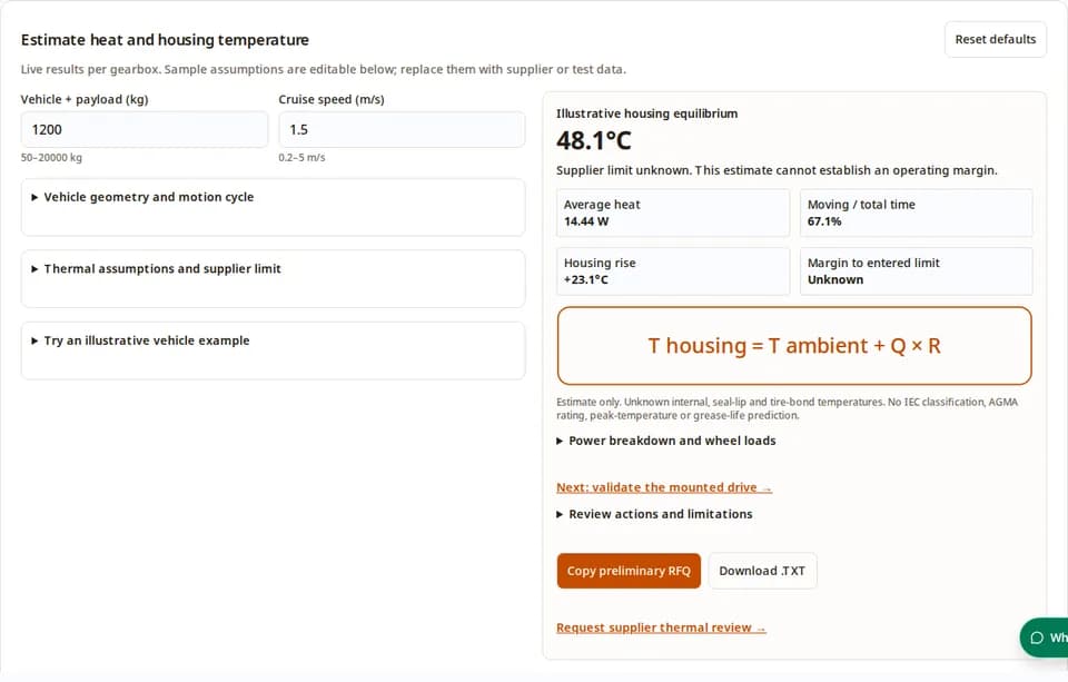
Live results per gearbox. Sample assumptions are editable below; replace them with supplier or test data.
1. What an AGV gearbox thermal review can decide
Use the calculator to compare assumptions and identify missing evidence. The report below supports the next engineering decision; it does not convert an estimate into a release approval.
| Conclusion | Basis / boundary | Next action |
|---|---|---|
| Balance losses against the installed heat path. | ISO/TR 14179 heat-balance context | Measure losses and temperature rise in the actual chassis. |
| Keep housing and contact-temperature reviews separate. | ISO/TS 6336-20 scuffing scope | Request a separate tooth-contact review for critical loads. |
| ED% alone does not specify motor duty. | ABB motor duty definitions | Record starting, electric braking and rest conditions. |
| Grease and seal life need component-specific evidence. | SKF grease model; seal catalogue | Request lubricant, seal and sensor-location limits. |
2. Reproducible calculation and power-flow limits
This is a project-defined lumped steady-state model, not an implementation of ISO/TR 14179 or an AGMA rating. Inputs use SI units; all results are per gearbox, with total traction shared equally between driven wheels.
Froll = m × 9.80665 × μ / N; a = v / tAcc
Eacc = (Froll + m × a / N) × v × tAcc / 2
Edec = |m × v / (N × tDec) − Froll| × v × tDec / 2
Ecruise = Froll × v × tCruise; ED = tMoving / tTotal
Qgear = (Eacc + Edec + Ecruise) × (1/η − 1) / tTotal + Pdrag × ED
Qtotal = Qgear + Qmotor,cycle-average; Thousing = Tambient + Qtotal × R
Ramps are linear between rest and cruise. Braking uses the magnitude of wheel-side mechanical power with the same loss multiplier as forward operation: this is an approximation, not a reverse-efficiency model. It does not place all vehicle braking energy in the gearbox; controller, motor and brake-resistor heat are outside this balance. Obtain direction-specific measured losses before design release.
3. What is known, assumed and still unknown
| Item | Tool default / status | How to replace it |
|---|---|---|
| Efficiency | 95%, illustrative; not tied to architecture or ratio | Supplier map at actual torque, RPM, lubricant and temperature. |
| Housing resistance | 1.6 K/W, illustrative; 0.95 and 2.4 in selected examples | Measure (housing − local ambient) / known net heat in the installed assembly. |
| Motor coupling heat | 8 W cycle average, illustrative; may persist at rest | Measured or validated coupled motor/gearbox thermal model. |
| Additional moving drag | 0 W default: can understate losses | Measured no-load loss, unless already included in the efficiency map. |
| Approved housing limit | Unknown; no margin is asserted until entered | Supplier limit for this assembly and measurement location. |
| Internal / tire / seal-lip temperature | Unknown; not calculated | Local instrumentation or a validated multi-node model. |
These constants are exposed assumptions, not measured fleet data or standard coefficients. The calculation ignores slopes, steering scrub, rotating inertia, uneven wheel sharing, housing geometry and temperature-dependent losses. An estimate above 150°C is flagged outside this model; 150°C is a screening guardrail, not a material rating.
4. Chassis heat paths and installation tradeoffs
Heat can leave through housing convection and radiation, shafts and mounting contacts. Chassis conduction helps only if the receiving structure remains a useful sink. Contact pressure, coatings, interface thickness and chassis temperature matter; plate thickness alone does not determine K/W.
| Choice | Potential benefit | Cost / mismatch risk | Verification |
|---|---|---|---|
| Direct structural flange | Additional conduction path | Stiffness and alignment constraints; hot chassis can feed heat back | Measure flange and chassis temperatures under load. |
| Thermal interface material | May reduce contact resistance | Thickness, compression, aging and bolt-load changes | Check clamp load and thermal cycling with production tolerances. |
| Isolation mount | Vibration isolation | Can impede heat flow and alter torque reaction | Compare noise and heat in a representative mount. |
| Forced ventilation | Additional heat rejection | Fan power, dust ingress, noise and maintenance | Validate blocked-filter and fan-failure conditions. |
5. Duty cycle, dwell and transient peaks
The default motion cycle is 3 s acceleration + 45 s cruise + 3 s deceleration + 25 s dwell: moving duty is 51/76 = 67.1%. This arithmetic describes time in motion, not a certified motor duty. ABB’s Annex D distinguishes S3 from duties involving significant starting and electric braking; the calculator therefore does not infer S1/S3/S5.
For a single thermal node under constant heat, T(t) = Tambient + Q × R × (1 − exp(−t/τ)), with τ = R × C. At 1τ, 3τ and 4τ the rise reaches about 63.2%, 95.0% and 98.2% of that model’s final rise. These are mathematical fractions; no universal gearbox time constant or test duration is claimed. Long cycles and short high-load peaks require transient measurement.
6. Lubricant and seal limits: use the exact assembly
Request the actual lubricant product, fill amount, approved temperature range, viscosity guidance and compatibility with the fitted seal. A grease family or elastomer acronym cannot establish an assembly operating limit. SKF’s seal catalogue relates sealing performance to material, medium, speed and local heat transfer.
Do not treat a universal “half life per 10°C” rule as a gearbox life model. SKF’s Y-bearing article describes a different temperature adjustment for its specified bearing and grease context. No grease service-life prediction is made here. A grease dropping point is also not an approved continuous operating temperature.
7. Failure modes the screen cannot clear
| Risk | Missing evidence | Mitigation / alternative |
|---|---|---|
| Misuse: cool housing taken as scuffing clearance | Tooth geometry, sliding, contact load and lubricant data | Request a separate flash-temperature assessment; reduce critical loading pending review. |
| Cost: premium grease or seals purchased without solving heat rejection | Installed heat-path and loss measurements | Identify the dominant loss/path before paying for component upgrades. |
| Mismatch: freezer or washdown assembly | Cold-start drag, condensation and ingress qualification | Cold-soak and environmental tests using the production assembly. |
| In-wheel PU tread or adhesive distress | Wheel-specific bond, tread and allowable local temperatures | Instrument the hub/bond region and obtain wheel-supplier limits; no universal 80°C threshold. |
| Hot bearing or clearance/preload shift | Bearing fits, materials and temperature distribution | Review tolerances and local temperatures; expansion can increase or decrease clearance. |
| Pressure or lubricant leakage | Seal pressure capability, vent design and ingress requirements | Use an approved sealing/vent solution; adding a vent does not guarantee an IP rating. |
8. Illustrative scenarios, not field case studies
The examples below are generated from the same transparent model as the tool. They are hypothetical, with no claimed customer, measured failure or service-life result. All housing limits remain unknown.
| Scenario | Premise | Model outcome | Decision |
|---|---|---|---|
| Warehouse AMR | 1200 kg; 1.5 m/s; 25°C ambient; η=95%; R=1.6 K/W; motor=8 W; drag=0 W; cycle 3/45/3/25 s | 67.1% moving; 14.44 W; 48.1°C housing | Load this example in the tool; replace assumptions and request the approved limit. |
| Sortation shuttle | 600 kg; 2.2 m/s; 32°C ambient; η=95%; R=0.95 K/W; motor=8 W; drag=0 W; cycle 2.8/55/2.8/10 s | 85.8% moving; 14.39 W; 45.7°C housing | Load this example in the tool; replace assumptions and request the approved limit. |
| Heavy pallet AGV | 3500 kg; 1 m/s; 35°C ambient; η=95%; R=1.6 K/W; motor=18 W; drag=0 W; cycle 4/50/4/30 s | 65.9% moving; 31.88 W; 86.0°C housing | Load this example in the tool; replace assumptions and request the approved limit. |
The freezer example is available in the tool, but does not predict grease breakaway torque. Comparing gearbox families at the same entered efficiency intentionally gives the same heat: an architecture label is not an efficiency map.
9. Mounted validation and release evidence
This is a proposed engineering test plan, not a quoted standard acceptance protocol. Agree the load cycle, stabilization criterion, component limits and shutdown criteria with the responsible engineer and supplier before testing.
| Step | Record | Acceptance basis |
|---|---|---|
| 1. Reproduce the installation | Mounting CAD, torque, wheel, enclosure, airflow and lubricant fill | Production-representative boundary conditions. |
| 2. Instrument the heat paths | Local ambient, housing, input flange, chassis, wheel and approved internal locations | Calibrated sensors and documented sensor attachment. |
| 3. Run representative and worst-case cycles | Torque, speed, starts, braking, dwell, motor current and temperatures | Approved component-specific limits and transient peaks. |
| 4. Confirm stabilization / repeatability | Full time histories with sampling interval and ambient drift | Agreed trend criterion; no universal 2–3 hour duration. |
| 5. Review before release | Thermal data, leakage, noise, wear, cold-start and mechanical checks | Documented supplier/engineering approval with unresolved risks closed. |
10. Supplier RFQ: close the evidence gaps
Export the preliminary RFQ from the tool and attach mounting CAD, payload distribution, wheel geometry, ramp/braking profiles, torque-speed logs, ambient envelope and any temperature traces. Ask for measured losses in both power-flow directions, no-load loss treatment, approved continuous and peak temperatures with sensor locations, lubricant/seal specifications and the validation conditions used.
Ask engineering about missing thermal data →Request a separate review for radial and overhung wheel loads, backlash, bearing life, braking safety and ingress protection. A thermal screen does not close those requirements.
Send thermal requirements for engineering review →11. Decision questions
Using the tool
Is this a gearbox thermal rating?
No. It is an uncalibrated heat-balance screen. Replace sample assumptions with supplier or test data and validate the mounted assembly before selection.
What if I do not know the housing temperature limit?
Leave the optional limit blank. The tool still estimates heat and housing temperature but reports the operating margin as unknown. Ask the supplier for the limit and sensor location.
Why does changing ratio not change the heat estimate?
Ratio changes calculated motor RPM. Heat depends on the entered efficiency and losses; without an efficiency map the model cannot infer how a new ratio changes losses.
Does dwell time eliminate motor heat?
No. The motor heat input is already a cycle-average value and remains in the balance during dwell. Use measured heat transfer across the complete cycle, including holding and charging.
Evidence and limits
Does a low housing temperature rule out scuffing?
No. Tooth contact flash temperature requires a separate geometry, load and lubricant assessment. ISO/TS 6336-20 addresses a different calculation from housing equilibrium.
Can ED% determine S3 or S5 duty?
No. ED% here is only moving time divided by total time. Starting heat significance, electric braking and de-energized rest must be known before assigning a motor duty type.
Does every 10°C rise halve grease life?
No universal factor is established here. Oxidation and service life depend on formulation and operating conditions. Use the lubricant supplier’s validated model; bearing-specific rules cannot certify gearbox life.
Can I use an infrared housing reading as oil or seal temperature?
No fixed offset is reliable for every design. Calibrate emissivity and compare with contact sensors; obtain manufacturer-approved internal or seal-location measurement guidance.
Validation and procurement
Is a thicker aluminum chassis always the best fix?
No. Contact area, interface resistance, chassis temperature, stiffness, corrosion and load paths all matter. Compare installed temperature rise and structural requirements before changing the mounting.
Does the freezer preset predict cold-start torque?
No. The preset uses illustrative steady-state assumptions. Cold breakaway torque, lubricant flow, condensation and seal compatibility need separate cold-soak testing.
How long should a thermal test run?
Repeat the representative cycle until temperature trends meet an agreed stabilization criterion, then check worst-case peaks. Duration depends on the assembly and boundary conditions; there is no universal time constant here.
What should I send with the RFQ summary?
Include the complete torque-speed cycle, ambient envelope, mounting CAD, temperature traces, lubricant and seal details, wheel requirements, approved limits and the evidence still missing.
12. Sources, scope and related reviews
Public source scope checked on . Standards abstracts establish scope; full calculation clauses may require licensed documents. Sample constants and hypothetical scenarios are identified above and are not attributed to these publications.
- ISO/TR 14179-1:2001 — Gear thermal capacity
Public abstract: analytical heat balance for mineral-oil gear drives, with reference ambient and sump conditions. It does not establish the sample efficiency, thermal resistance or grease limits used here.
- ISO/TS 6336-20:2022 — Scuffing / flash temperature
Public abstract: scuffing assessment using contact temperature. Housing equilibrium alone cannot establish tooth-contact scuffing capacity.
- ABB Technical Application Papers — Motor duty types, Annex D
S3 assumes negligible starting heat; S5 includes starting and electric braking. These are motor duty descriptions, not gearbox certifications.
- SKF — Improved grease-life model for Y-bearings
The specific Y-bearing model uses a temperature-dependent life adjustment within a stated range. Its limits and bearing context prevent direct transfer to arbitrary gearbox grease.
- SKF — Industrial shaft seals catalogue
Seal selection depends on material, medium, shaft speed, friction and local heat transfer. A housing sensor does not directly measure seal-lip temperature.
Continue the same selection task with duty-cycle review, supplier sizing, or AGV / AMR gearbox integration.
Review policy: recheck sources and assumptions within six months (next review 2027-05-01), or earlier when supplier data or the model changes. Send corrections through our contact page.
Send your thermal review requirements →