
By Robotized Gearbox · Published September 27, 2026 · Reviewed
1 to 1 Right Angle Gearbox: Torque & Heat
Estimate running torque and heat loss for a 90° miter drive. Edit the inputs, download your assumptions, then check the selection limits below.
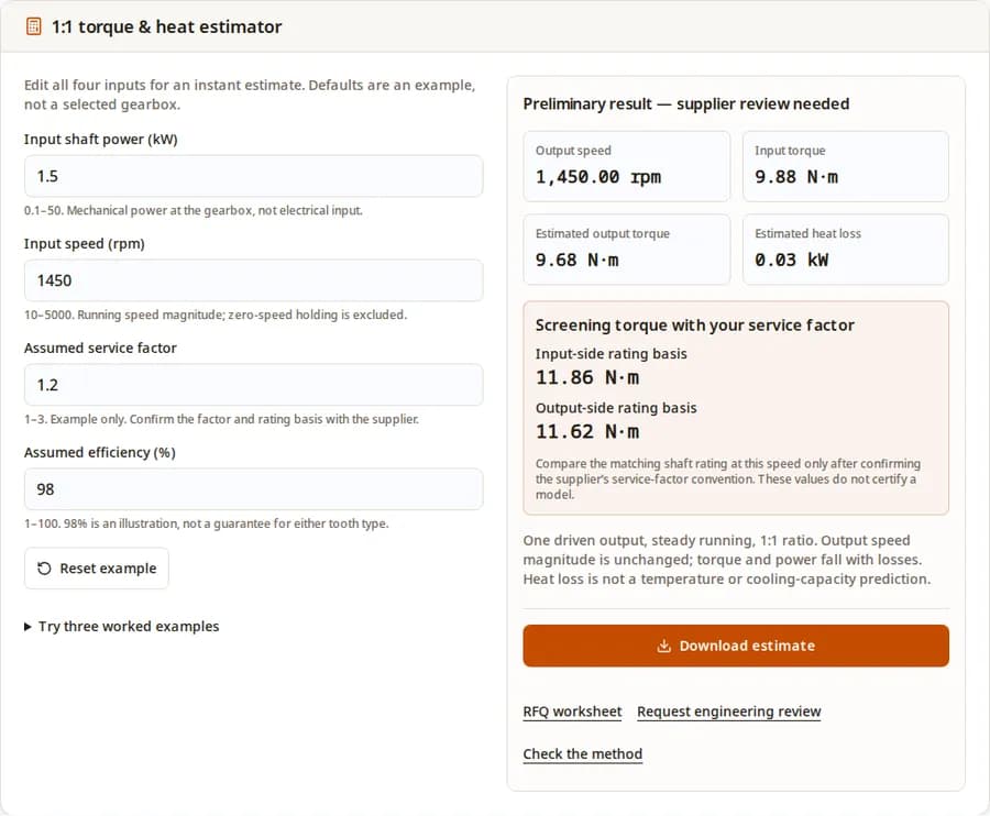
1:1 torque & heat estimator
Edit all four inputs for an instant estimate. Defaults are an example, not a selected gearbox.
0.1–50. Mechanical power at the gearbox, not electrical input.
10–5000. Running speed magnitude; zero-speed holding is excluded.
1–3. Example only. Confirm the factor and rating basis with the supplier.
1–100. 98% is an illustration, not a guarantee for either tooth type.
Try three worked examples
Preliminary result — supplier review needed
- Output speed
- 1,450.00 rpm
- Input torque
- 9.88 N·m
- Estimated output torque
- 9.68 N·m
- Estimated heat loss
- 0.03 kW
Screening torque with your service factor
- Input-side rating basis
- 11.86 N·m
- Output-side rating basis
- 11.62 N·m
Compare the matching shaft rating at this speed only after confirming the supplier’s service-factor convention. These values do not certify a model.
One driven output, steady running, 1:1 ratio. Output speed magnitude is unchanged; torque and power fall with losses. Heat loss is not a temperature or cooling-capacity prediction.
What the estimate can tell you
A direction change, with no speed reduction
A 1:1 miter pair preserves speed magnitude across the 90° shaft arrangement. If your load needs lower speed, specify an additional reduction stage. [1]
Efficiency is a model-specific assumption
PowerGear advertises 98% efficiency; its P tables qualify efficiency at maximum load. Neither source establishes the same value for every miter drive. [2] [3]
A torque number is only a screening step
KHK separates provisional torque selection from verification under actual operating conditions. Check the assembled gearbox’s continuous, peak, speed and thermal ratings. [1]
Backlash and speed need a specific model
Graessner lists separate model values and rating conditions. Specify the required output backlash and duty; there is no single limit shared by all 1:1 drives. [3]
Method: keep the shaft and rating basis explicit
For steady rotation, P = T × angular speed. Converting kW and rpm gives T = (60,000 / 2pi) × P / n ≈ 9550 × P / n, in N·m. The rounded constant is sufficient for this preliminary estimate. The single-output model uses your efficiency and assumed service factor SF. In these equations, efficiency is a fraction (98% = 0.98).
| Quantity | Equation | Interpretation |
|---|---|---|
| Output speed | n_out = n_in | Same speed magnitude at a 1:1 ratio. |
| Input torque | T_in = 9550 × P_in / n_in | Mechanical input shaft power, not electrical consumption. |
| Output torque | T_out = efficiency × T_in | Available running torque under the assumed losses. |
| Screening torque | T_screen = SF × T_shaft | Compare input to input or output to output; confirm how the supplier applies SF. |
| Heat loss | P_loss = P_in × (1 − efficiency) | Power dissipated in kW. Does not predict housing temperature. |
Inputs are limited to 0.1–50 kW, 10–5000 rpm, SF 1–3 and efficiency 1–100% for this tool. These are software bounds, not approved operating limits. At 100% efficiency the model is ideal and loss-free. Service factor 1.2 and 98% efficiency are editable examples.
Three reproducible screening examples
Illustrative operating points, not tested installations or product recommendations. Load them under “Try three worked examples” in the tool. All use n_out = n_in and the equations above; results are rounded to two decimals.
| Scenario and inputs | Running torques | SF-adjusted screening | Loss and decision |
|---|---|---|---|
| Conveyor: 1.5 kW, 1450 rpm, 98% efficiency, SF 1.2 | Input 9.88; output 9.68 | Input 11.86; output 11.62 | 0.03 kW. Check duty, starting load and the relevant shaft rating. |
| Slow drive: 0.5 kW, 100 rpm, 95% efficiency, SF 1.5 | Input 47.75; output 45.36 | Input 71.63; output 68.04 | 0.03 kW rounded. Low power still creates substantial torque at low speed; check shaft loads. |
| Heat review: 50 kW, 3000 rpm, 98% efficiency, SF 1.2 | Input 159.17; output 155.98 | Input 191.00; output 187.18 | 1.00 kW. Request a thermal check at the intended duty and ambient conditions. |
Reproduce the default estimate
For a general reduction stage, use the gearbox sizing calculator. To prepare the installation details, review our engineering resources and load and life validation inputs.
Download the RFQ worksheetSelection checks: known versus still unknown
A result does not select a housing size. Use the following review sequence after confirming which shaft the catalog rating describes. Manufacturer tables show why operating conditions matter. [1] [3]
| Check | Known from this tool | Still needed |
|---|---|---|
| Continuous torque | Estimated shaft torque at one running point | Load profile, catalog shaft basis, rated speed and supplier-approved service factor. |
| Starting / reversing / stopping | Not calculated | Load inertia, acceleration, peak duration, emergency-stop events and allowable peak ratings. |
| Thermal duty | Estimated mechanical power loss | Duty cycle, ambient temperature, mounting, oil specification and permitted thermal power. |
| Shafts and bearings | Not calculated | Radial and axial forces, load position, coupling alignment and bearing-life requirement. |
| Positioning | Not calculated | Output backlash measurement condition, torsional stiffness and reversal repeatability. |
| Multiple driven outputs | Outside the single-output model | Branch torque distribution and combined input loading. |
Straight versus spiral miter: compare the assembled unit
KHK offers both tooth forms across multiple materials and accuracy grades. Tooth form alone does not establish the assembled gearbox’s efficiency, acoustic performance or price. [1]
| Decision | Straight miter candidate | Spiral miter candidate | Evidence to request |
|---|---|---|---|
| Geometry | Straight tooth trace | Curved tooth trace; matching hand matters | Approved gear pair and shaft arrangement. |
| Noise and vibration | Evaluate at your running point | Evaluate at the same running point | Measured noise and test conditions; no universal dB difference established here. |
| Speed and efficiency | No universal value established | 98% is one family example [2], not a class guarantee | Torque-speed and efficiency data under your load. |
| Cost and lead time | Unknown until configured | Unknown until configured | Comparable quotes including backlash option, bearings, seals and inspection. |
When 1:1 is the wrong ratio
| Requirement | Candidate | Tradeoff / review |
|---|---|---|
| Same speed, 90° shaft turn | 1:1 miter gearbox | Check torque, packaging and losses; no torque multiplication. |
| Lower speed and higher torque | A right-angle reduction stage or reduction plus a 1:1 turn | Choose the overall ratio first; additional stages affect space, loss and cost. |
| Coaxial shafts with no speed change | Direct coupling where the layout permits | Review alignment and coupling loads; a right-angle stage may add unnecessary parts. |
| Load holding with power removed | An independently validated holding/braking arrangement | Do not rely on assumed worm self-locking. Its effectiveness depends on operating conditions. [4] |
For other ratios, use the gearbox ratio guide to establish the speed relationship, or the AGV & AMR drive gearbox calculator for mobile robotic applications.
Risks and practical mitigations
Misuse: treating running torque as a peak limit
Emergency-stop loading depends on inertia and stopping time. Supply the actual motion profile and check the model’s permitted peak events. No universal “300%” multiplier is established here.
Cost: buying precision without a tolerance budget
Specify allowable output error and stiffness before paying for tighter backlash. Compare matched quotes and include inspection, lubrication, maintenance and replacement availability.
Mismatch: using efficiency as a cooling approval
Even the 98% example loses 1 kW at 50 kW input. Ask the supplier to check continuous duty and ambient conditions. Revisit duty, housing or cooling if the thermal check fails.
Sources, dates and evidence limits
Reviewed September 27, 2026. Sources below support the stated geometry and manufacturer-specific examples. They do not establish a universal service-factor table, cooling threshold, efficiency by tooth type or guaranteed life. This page’s examples are calculations, not measured performance.
- [1] KHK — Miter Gears catalog (2023), printed pp. 302–307
1:1 geometry, mating pairs and strength-selection assumptions. Individual gears, not complete gearbox ratings.
- [2] Nidec Drive Technology — PowerGear series
Example of a commercial spiral-bevel family offering 1:1 and quoting 98% efficiency. Not an efficiency guarantee for other units.
- [3] Graessner — PowerGear P performance tables (2020)
Model-specific speed, torque, backlash and efficiency conditions. Historical reference; request the current table for a purchase.
- [4] Oriental Motor — Worm Gearhead, self-locking conditions
Explains why lubrication, tooth condition, shock and vibration can defeat self-locking.
Frequently asked questions
Ratio and arrangement
What does a 1 to 1 right angle gearbox do?
It redirects rotation through perpendicular shafts while keeping the same speed magnitude. Real output torque is lower than input torque because of losses. See the geometry source [1] and power-balance method above.
Is every miter gearbox a 90-degree drive?
This page covers the common 90-degree, 1:1 arrangement. Angular miter gears also exist, so specify both shaft angle and ratio on the drawing; the KHK catalog [1] includes other shaft angles.
Can it replace a speed reducer?
Only if the required output speed already matches the gearbox input. If a load needs 150 rpm from a 1500 rpm input, the speed equation requires 10:1 overall reduction. A 1:1 stage alone cannot provide it.
Does 1:1 tell me the output rotation direction?
No. Record the viewing direction for each shaft and obtain the supplier’s rotation diagram. Ratio alone does not specify clockwise or counterclockwise motion, or suitability for reversing duty.
Calculation and limits
Is input power the motor’s electrical consumption?
No. Enter mechanical power reaching the gearbox input shaft. Electrical input includes motor and drive losses. A nameplate power value may represent rated output rather than the actual operating point.
Why is 98% the default efficiency?
It is an illustrative assumption consistent with one commercial family [2]. It is not measured data for your gearbox. Use the selected model’s efficiency at your load, speed and lubricant temperature.
Does the service factor guarantee gearbox life?
No. It is a provisional multiplier for discussion. Confirm the supplier’s factor convention and check continuous, peak and thermal limits separately; do not apply a factor twice to an already adjusted rating.
Can the tool calculate starting or holding torque?
No. The running-power equation divides by speed and cannot determine zero-speed holding torque. Starting, reversing and braking require the load torque, inertia and acceleration or deceleration profile.
Selection and purchase
Can I use the result for a gearbox with two driven outputs?
Not without a load-distribution analysis. This tool assumes one driven output. Supply the torque and duty of every branch so the input mesh, each output shaft and bearings can be checked.
Will a spiral-bevel unit always be quieter or more efficient?
A tooth-form name alone is insufficient. Compare assembled-unit measurements under equal speed and load, with the same measurement method. The available sources do not establish a universal dB advantage.
Can a worm alternative hold a suspended load by self-locking?
Do not assume it can. The manufacturer warns that self-locking depends on lubrication, tooth condition, shock and vibration [4]. Specify an independently validated holding or braking system for the application.
What should I send with the RFQ?
Download the estimate and RFQ worksheet. Add continuous and peak load data, shaft speeds, duty cycle, rotation, ambient temperature, mounting drawing, shaft loads, required backlash, quantity and delivery needs.
Turn the estimate into a reviewable RFQ
Download your inputs and results from the tool, complete the worksheet, and attach the load profile and mounting drawing. Ask engineering to confirm the rating basis, duty and model limits before ordering.