
Require a load reference
A wheel-drive product needs a defined output-bearing arrangement and mounting geometry. Manufacturer example.
Supplier screening · free preliminary RFQ tool
Screen an AGV drive wheel gearbox supplier: estimate wheel torque, ratio and external loads, then compare the evidence a supplier should return. Start with the editable example below.
Prepared by Robotized Gearbox · Buyer engineering and procurement guide
This page is a buyer screening method, not a supplier ranking. Its calculations are transparent first-principles estimates; the evidence below supports the review method, not a promise that any particular gearbox meets it.
A wheel-drive product needs a defined output-bearing arrangement and mounting geometry. Manufacturer example.
A basic bearing life calculation has specific fatigue assumptions. ISO 281 scope.
Braking qualification needs the truck and its system, beyond a gearbox torque label. ISO 3691-4 scope.
Units: mass m in kg; g = 9.80665 m/s²; diameter D in mm; speed v in m/s; acceleration a in m/s²; n driven wheels; η as a fraction. Grade and forward acceleration are assumed simultaneous. Rolling coefficient 0.02 and efficiency 94% are editable example assumptions, not material or product ratings.
| Quantity | Example assumptions | Result / meaning |
|---|---|---|
| Vehicle | 1,200 kg; 2 driven wheels; 200 mm wheel; 3% uphill grade | Equal traction sharing, straight-line travel |
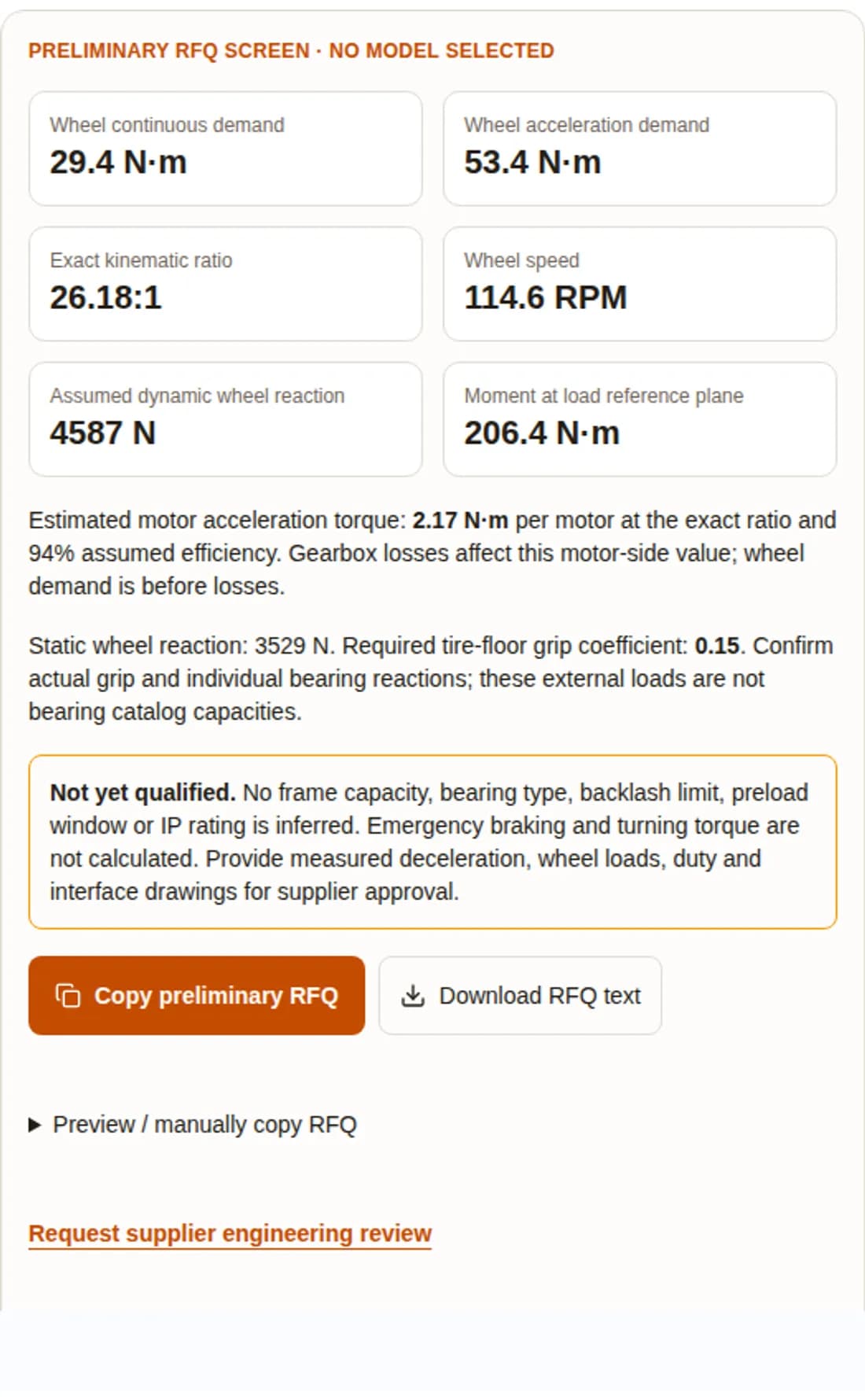
| Wheel demand | Rolling 0.02; acceleration 0.4 m/s² | 29.4 N·m continuous; 53.4 N·m during acceleration, per wheel |
| Wheel speed / ratio | 1.2 m/s; motor 3,000 RPM | 114.6 RPM; 26.18:1 exact speed ratio |
| Motor-side demand | 94% efficiency at the exact ratio | 2.17 N·m per motor during acceleration |
| External wheel load | 60% weight share; 1.3 radial multiplier; 45 mm offset | 4,587 N assumed dynamic reaction; 206.4 N·m external moment |
Exclusions: no motor/rotor inertia, aerodynamic resistance, trailer drag, turning, floor-joint impact prediction, downhill stopping or thermal time model. A displayed acceleration demand is not a gearbox peak capacity, and the steady uphill value is not an RMS duty rating.
The following is an engineering review checklist, not a performance ranking. No universal vehicle-mass cutoff establishes whether a direct drive or reducer is suitable. Ask each bidder for its configured torque-speed-temperature envelope.
| Option | Potential benefit | Evidence needed / fit risk |
|---|---|---|
| In-line planetary hub | Coaxial packaging and reduction between motor and wheel | Check axial space, efficiency map, output load support and wheel interface |
| Right-angle geared drive | Can relocate the motor around chassis packaging constraints | Check envelope, losses and bearing support for the actual wheel offset |
| Cycloidal reducer | Alternative reduction and stiffness architecture | Check permitted speed, reversing duty, efficiency and output bearing limits |
| Direct-drive wheel motor | Eliminates gearbox mesh and its backlash | Check low-speed continuous torque, cooling, current, braking, mass and service access |
| Integrated steer-drive | Combines traction and steering interfaces | Separate steering-axis loads from wheel rotation loads and validate controls |
Catalog performance, prices, acoustic levels and lead times are configuration-specific and are unknown here. Obtain equivalent dated offers instead of assuming that one architecture is always lighter, cheaper or thermally superior.
The tool estimates Fstatic = m g × driven weight share × cosθ / n; Fdynamic = Fstatic × entered multiplier; M = Fdynamic × L. These are external reactions at a stated plane. Internal bearing forces depend on support spacing, contact angles, axial loads and load distribution. A dedicated wheel-drive product illustrates why the output-bearing design deserves separate review.
SKF explains L10 = (C/P)ᵖ in millions of revolutions and L10h = 10⁶ L10 / (60 N), with p = 3 for ball bearings and 10/3 for rollers. Use bearing speed N, not automatically motor speed. The tool lacks bearing geometry, C and equivalent bearing load P, so it deliberately does not display a life estimate.
| Review item | Known from this screen | Supplier evidence required |
|---|---|---|
| External loads | Weight share, dynamic multiplier, offset assumptions | Measured wheel reactions, axial/turning loads and drawing reference planes |
| Bearing fatigue | Basic life methodology only | Bearing IDs, support reactions, C/P, speed spectrum, lubrication and contamination factors |
| Bearing arrangement | No bearing type selected | Combined-load stiffness and life for the proposed ball/roller arrangement |
| Preload / cold drag | No universal acceptance window | Design-specific tolerances, temperature, seals, grease, speed and run-in procedure |
| Hot operation | Not predicted by this tool | Loaded thermal run and cold-start test at intended ambient extremes |
SKF recommends calculation and application testing for new preload designs. A generic negative clearance or cold starting torque window cannot qualify every hub size. ISO 281 addresses bearing fatigue; it is not a guarantee against wear, leakage or corrosion.
Navigation type is RFQ context only. Allocate permissible wheel motion error from docking accuracy, encoder placement, controller behavior, tire compliance and reversal frequency. A LiDAR or QR label alone does not establish a gearbox backlash limit.
For illustration, a 200 mm wheel with 6 arcmin output angular deadband corresponds to rθ = 100 mm × (6π / 10,800) ≈ 0.175 mm of rim displacement for that angle. This is not a prediction of vehicle localization drift; unequal wheel errors, floor slip and sensor fusion change the outcome.
Turning adds tire-floor shear and steering-axis moments. The previous single contact-patch expression cannot be applied directly as wheel-shaft torque without track width, contact geometry and a vehicle force model. Request a measured turning-current/torque trace at maximum laden mass and validate the gearbox against repeated reversals.
Review the wheel motion error budgetSupply a torque-speed-time cycle, hours per shift, enclosure temperature, wheel loads and mounting heat path. Require a loaded run at representative conditions, including cold start where applicable. A motor duty label or high catalog efficiency alone does not establish gearbox thermal capacity.
| Application | Request from supplier | Acceptance decision |
|---|---|---|
| Continuous operation | Torque/speed cycle, stable temperatures, permitted grease/seal limits | Accept only within component limits at your ambient and mounting conditions |
| Cold storage | Minimum-temperature start current, drag, seal behavior and lubricant data | Confirm cold start and warm operation; ambient range must be in the written offer |
| Washdown | Actual ingress test conditions, chemicals, seal compatibility and corrosion protection | An IP label alone does not prove washdown chemistry or hygienic suitability |
| Dust / debris | Sealing arrangement, abrasion exposure, cleaning and maintenance intervals | Agree an inspection and replacement plan with access in the assembled vehicle |
ISO 3691-4:2023 covers safety requirements and verification for driverless trucks and their systems. Its public scope is not evidence for a fixed 2.8× gearbox torque requirement. This page does not calculate a stopping torque or claim compliance.
Send the supplier the worst downhill/loaded condition, speed, required deceleration, stopping distance, brake location, reflected inertia, drive control behavior and expected stop count. Capture transient torque and tire slip during vehicle tests. A motor-mounted brake, regenerative stop and mechanical wheel brake can impose different drivetrain loads.
Specify both normal and emergency stopping tests with the vehicle safety engineer, using the applicable full standards and project requirements. Turning and braking acceptance remain open until those tests pass.
No published failure dataset, customer warranty audit or verified competitor quote supports a numerical supplier ranking here. Mark missing evidence as not demonstrated; do not award an assumed pass.
| Gate | Pass evidence | Hold / next action |
|---|---|---|
| Configured performance | Signed torque/speed/duty limits and configured part number | Request operating envelope if only a headline torque is provided |
| Wheel loads / life | Drawing reference, simultaneous loads, bearing calculations | Reconcile load planes and assumptions before comparing catalog radial loads |
| Manufacturing traceability | Agreed dimensional, material, heat-treatment and run-in records | Define sample inspection scope and traceable serial/batch IDs |
| Interface compatibility | Approved pilot, shaft, bolt pattern, rim and motor drawings | Perform CAD fit and tolerance review; similar frame size is insufficient |
| Sample / vehicle validation | Agreed thermal, reversal, leakage, stopping and acceptance records | Hold production release until deviations are resolved |
| Commercial / service | Dated quote, lead time, MOQ, tooling, warranty and spare terms | Use a written offer; no universal price or turnaround is claimed |
Robotized Gearbox is a candidate for engineering review, not an automatically qualified match. Ask for a configured proposal and evidence against this same matrix. The Neugart reference is an example of public product documentation, not an assertion of equivalence.
Hypothetical buyer arithmetic in USD, not market pricing or field reliability data. Assume a five-year / 20,000-hour horizon. Replacement counts below are sensitivity inputs; no supplier is assigned a failure rate. Taxes, discounting, energy and residual value are excluded.
| Input / outcome | Bid A scenario | Bid B scenario |
|---|---|---|
| Initial unit + integration | $180 + $40 = $220 | $280 + $40 = $320 |
| Each replacement incl. labor | $180 + $150 = $330 | $280 + $150 = $430 |
| Downtime per replacement | 2 hours × $50/h = $100 | 2 hours × $50/h = $100 |
| Zero replacements | $220 | $320 |
| One replacement | $220 + $330 + $100 = $650 | $320 + $430 + $100 = $850 |
| A has two replacements; B none | $220 + 2 × ($330 + $100) = $1,080 | $320 |
The lower purchase price wins if neither fails under these assumptions; different replacement outcomes can reverse the decision. Request field evidence before assigning probabilities. Include tooling, spare inventory, freight and maintenance in your actual purchasing model.
500 kg, 2 drives, 160 mm wheels, 1.5 m/s, 0.6 m/s², 1% grade. With rolling coefficient 0.02: 17.9 N·m wheel acceleration demand and 16.76:1 ratio at 3,000 RPM. Frequent spin turns remain outside this model; measure reversal torque before sample approval.
Default 1,200 kg inputs yield 53.4 N·m acceleration demand and 26.18:1 ratio. With 60% driven weight, the minimum required grip coefficient is about 0.15. Test actual floor/tire traction and bearing loads instead of treating the mass class as a frame selection.
3,000 kg, 2 drives, 250 mm wheels, 0.8 m/s, 0.3 m/s², 4% grade: 166.5 N·m acceleration demand, 40.91:1 at 2,500 RPM. At 60% weight share and 1.3 radial factor, external dynamic reaction is about 11.46 kN per drive. Request a configured rating and thermal test; no automatic frame match is made.
| Packet item | Include | Why it changes the decision |
|---|---|---|
| Vehicle and wheels | Gross mass, driven/caster weight share, wheel geometry, measured floor loads | Separates tractive demand from bearing support loads |
| Motion and stops | Speed, acceleration, grades, turning cycle, deceleration and stop count | Defines normal and transient load cases |
| Motor and mounting | Motor curve, shaft/pilot drawing, rim/bolt pattern, load reference plane | Checks ratio feasibility and interface fit |
| Duty and environment | Torque-speed-time cycle, ambient range, enclosure, cleaning and ingress exposure | Defines thermal, seal and lubrication tests |
| Acceptance and commercials | Life target, error budget, sample criteria, annual volume, delivery and service terms | Makes supplier responses comparable and reviewable |
Use the tool’s copy/download output as a preliminary attachment. Unknown loads, braking, preload, life and product capacity must stay marked as unresolved until evidence is returned.
Public primary sources checked on . Standards editions and product data can change; confirm applicability at design release. Public abstracts do not replace the full standards. No independent gearbox test dataset or comparative price survey is available for this page.
Basic and modified bearing rating life; basic life uses 90% reliability. Does not establish a complete wheel-hub load model or guarantee service life.
Vehicle/system safety requirements and verification. The public scope does not establish a universal gearbox emergency-stop torque multiplier. Confirm the applicable edition for your project.
Preload depends on design, operating temperature and housing elasticity. New designs require calculation and application testing; no universal micrometre or drag-torque window is adopted here.
L10 and L10h equations, ball/roller exponents and the influence of lubrication, contamination and installation on actual life.
A named manufacturer example of a wheel-drive gearbox with a dedicated output bearing arrangement. Ratings and load reference geometry must be read for the configured size; this is not a rating for Robotized Gearbox products.
The architecture matrix, scorecard and cost scenarios are editorial decision aids. Numerical defaults are transparent assumptions; the worked examples are reproducible calculations. They are not field observations, supplier guarantees or proof of product compliance.
Preliminary straight-line wheel torque, speed, kinematic ratio, motor torque and external wheel reaction/moment. It does not select a frame, rate bearings or certify a vehicle.
No. Enter total operating mass, including the vehicle and payload. If towing trailers, supply the trailer load and resistance separately; this tool excludes towing.
Casters can carry much of the weight while the driven wheels supply all traction. Enter the measured weight share on driven wheels; do not divide total vehicle weight by driven-wheel count without checking it.
Only as a straight-travel screening example. Roller geometry, lateral forces and direction-dependent traction require a dedicated model and supplier review.
There is no universal payload cutoff between geared and direct drive. Compare the actual motor torque-speed-temperature envelope, wheel space, braking and duty at the same operating points.
No universal limit follows from the navigation label alone. Allocate a wheel motion error budget and test reversal, tire compliance, encoder location and controller correction in the actual vehicle.
It is the motor-to-wheel speed ratio at the entered speed, not a standard product ratio. A supplier must check an available ratio against the motor torque-speed curve and required maximum travel speed.
Wheel-side traction demand is force multiplied by rolling radius. Efficiency enters the motor-side estimate: motor torque equals wheel torque divided by ratio and total gearbox efficiency.
No. Bearing type, spacing, stiffness, lubrication and combined loads must be assessed together. Require calculations and tests for the proposed arrangement rather than selecting by bearing type alone.
No. Require limits for the exact assembly, test temperature, lubricant, seals, speed, run-in condition and measurement method. Validate cold start and hot steady operation.
A fixed multiplier is not used here. Define deceleration, downhill load, reflected inertia, brake location, transient peaks and event count, then verify stopping performance at vehicle level.
No. Basic rating life describes rolling fatigue at a stated statistical reliability under its assumptions. Contamination, wear, seals and installation can limit service life earlier.
Request a configured part number, continuous/peak torque and speed limits, load reference drawing, bearing life assumptions, thermal test conditions, backlash measurement method and CAD interface drawing.
Only after matching speed, life, load direction, offset reference, duty and simultaneous moment/axial loads. A radial number without those conditions is incomplete.
A quality management certificate alone does not validate your torque, life or stopping requirements. Check its scope and validity, then qualify the configured assembly.
Agree a load/speed/ambient duty cycle, measured torque and temperature, backlash before/after, leakage acceptance, cold-start procedure and vehicle braking/turning tests, with traceable sample IDs.
No. The cost table is a labeled hypothetical example. Obtain dated quotes and use measured maintenance and downtime data before making a purchase decision.
No. Request a dated written offer covering prototype and production lead time, MOQ, tooling, exclusions, warranty, service procedure and spare-stock responsibility.
No. Check ratio, rotation, shaft/pilot tolerances, wheel offset, motor clamping, load ratings, sealing and thermal behavior. Release a replacement only after drawing and sample validation.
Download the worksheet, mark unknown inputs explicitly, attach drawings and measured vehicle loads where available, and request an engineering review. A calculator default is not measured vehicle data.
Attach your preliminary RFQ, drawings and missing-data list. Ask each supplier to return the configured performance envelope and a sample test plan before ordering production units.