
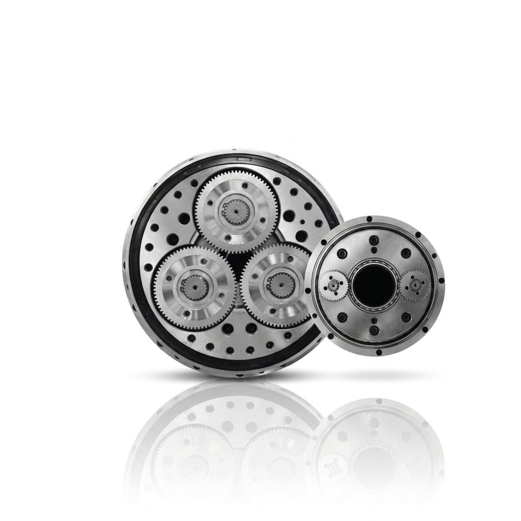
Lost Motion vs. Backlash in Robotic Gearboxes: How Sourcing Teams Read Hysteresis Curves and Prevent Position Drift
Lost motion vs. backlash in robotic gearboxes: read hysteresis curves, estimate tool-tip error, and use an RFQ checklist to request comparable supplier test data.
Lost motion vs. backlash in robotic gearboxes is a procurement question about test conditions, not just two catalog numbers. Backlash describes mechanical clearance; lost motion characterizes angular movement under a specified small reversing torque. Neither number alone predicts a loaded robot's tool-center-point (TCP) accuracy.
A reducer can satisfy a low-backlash specification yet allow noticeable tool-tip movement because of torsional compliance. For a sourcing team comparing precision cycloidal (RV), strain wave (harmonic), and planetary reducers, the useful evidence is the supplier's torque–angle curve, the measurement convention, and the application's error budget.
Executive Summary for Sourcing & Engineering Teams
- Compare protocols first: Nabtesco and SPINEA describe lost motion at ±3% of rated torque on the hysteresis centerline. Confirm the method for each proposed model rather than extending that convention to every gearbox.
- Keep the metrics separate: A zero-torque loop opening includes frictional hysteresis and must not automatically be labeled pure tooth clearance.
- Translate angles into an error budget: A 1 arcmin output-angle change gives approximately 0.349 mm of tool-tip movement at a 1,200 mm perpendicular lever arm, before other robot errors.
- Request evidence: Ask for a locked-input torque–angle report, stiffness over the working torque range, and agreed acceptance conditions.
Published and last reviewed: October 27, 2026. Scope: Global sourcing and engineering screening of precision reducers for robot joints and rotary positioners. Limits: This is a document-review and RFQ guide, not an installed-robot accuracy certification. Numerical examples below are calculated scenarios, not factory measurements or customer results. Final selection requires the actual torque-speed duty cycle, inertia, mounting, temperature, and servo response.
Preparing a supplier comparison? Send the joint load profile, reach, and target positioning tolerance for an application review, or use the checklist below before requesting quotations.
1. Deconstructing the Mechanics: Backlash, Lost Motion, and Rigidity
Use the selected manufacturer's definitions and test diagram. Terms that look identical in two catalogs can use different torque levels, loading histories, or curve-reading conventions. Robot-level performance tests and component-level hysteresis measurements answer different questions; a robot accuracy standard does not establish a universal reducer test protocol.
RFQ evidence to request separately
Mechanical backlash -> clearance and probing-torque convention
Lost motion         -> low-load reversal angle and test-torque convention
Torsional stiffness -> torque/angle slope over the working load range
Angular hysteresis  -> loading/unloading separation at a stated torque
These values overlap physically; they are not independent terms to add.
1.1 Pure Mechanical Backlash
Pure mechanical backlash is free rotational play from clearance between mating elements. A practical test must specify how the input and housing are restrained and how much probing torque is used. Bearing friction and elastic deflection make a nominally zero-load test difficult to interpret.
The zero-torque width of a hysteresis loop is not sufficient to isolate pure clearance. Nabtesco's backlash glossary distinguishes mechanical backlash from friction-related angular hysteresis. Require the supplier to identify which metric its quoted “backlash” value represents.
1.2 Lost Motion
Lost motion describes output angular movement under a defined low reversing torque and can include clearance, contact settling, and compliance. SPINEA's TwinSpin explanation uses the centerline angles at ±3% of nominal torque with the input and housing fixed. The chosen model's catalog remains the acceptance reference.
For this convention, subtract the centerline angle at negative test torque from that at positive test torque. Do not substitute the width between loading and unloading branches at one torque. A backlash-free mesh can still have measurable lost motion because its components deform under load.
1.3 Torsional Rigidity and Spring Rates
Torsional stiffness is the local ratio of torque change to angular change:
K = delta T / delta theta
Incremental deflection within one constant-stiffness region = delta T / K
Use consistent units. A stiffness in Nm/rad is not numerically interchangeable with Nm/arcmin; multiply Nm/rad by π/10,800 to obtain Nm/arcmin. Also check whether the value covers the gear component alone or the assembled reducer and output bearings.
The Harmonic Drive reducer catalog, printed pages 20–21, describes three spring constants, K1, K2, and K3, with model-specific transition torques T1 and T2. Calculate deflection piecewise, preserving the accumulated angle at each transition. Do not assign universal 20% and 50% boundaries or use the high-load slope for the entire curve.
Nabtesco's torsional-rigidity glossary instead describes a catalog stiffness slope over 50–100% of rated torque. A single slope can therefore be valid when its interval is stated; it is inadequate for predicting behavior outside that interval without more data.
2. Anatomy of the Gearbox Hysteresis Curve
A factory hysteresis curve plots applied output torque against output angle while the input is locked. For a model whose procedure calls for rated-load cycling, a sequence can be 0 → +TN → 0 → -TN → 0, where TN is the model's rated output torque. Use the manufacturer's approved load cycle and preconditioning.
The diagram below illustrates the reading conventions. It is schematic, not to scale; the low-torque spacing is exaggerated for visibility. It is not a test certificate.
Figure reading: Follow the dashed centerline to the positive and negative low-torque levels to determine lost motion. The orange zero-torque opening is angular hysteresis; the green tangent is a local stiffness slope. The drawing alone cannot separate tooth clearance from friction.
How to Review the Supplier's Test
- Restraint: Confirm which input member and housing surfaces are fixed. Request fixture-compliance characterization or correction; no real fixture has zero deflection.
- Loading: Record rated torque, actual positive and negative endpoints, ramp rate, dwell, and preconditioning cycles. The quasi-static ramp must limit inertial effects.
- Conditions: Record mounting, lubricant, temperature, and assembled configuration. Compare quotations under matching conditions.
- Measurement: Ask for calibrated torque and angle sensors, accuracy, uncertainty, and raw data. Encoder bit count alone does not establish measurement accuracy.
- Acceptance: Agree whether the limit is a maximum or typical value, how curve points are read, and how measurement uncertainty affects a borderline result.
Key Metrics Derived from the Loop
- Angular hysteresis: The branch separation in angular units at a specified torque. Friction contributes to it. Energy dissipated per cycle is the enclosed torque–angle area in Nm·rad (joules), not an angular width in arcminutes.
- Centerline: The midpoint of the two branches at each common torque, when that is the supplier's stated convention.
- Lost motion: The centerline angle difference between positive and negative low test torque for the convention illustrated here.
- Loaded deflection: The angle on the relevant loading or unloading branch at the actual working torque, relative to a stated reference.
3. Technology Architecture Comparison: RV Cycloidal vs. Harmonic vs. Precision Planetary
Compare models with the same load, envelope, ratio, and acceptance method. Architecture names and vendor precision-grade labels cannot establish a common numeric specification.
This table is a sourcing framework, not a measured ranking or a cross-brand performance guarantee:
| Selection parameter | RV / cycloidal proposal | Strain wave / harmonic proposal | Precision planetary proposal | Evidence to request |
|---|---|---|---|---|
| Mechanical backlash | Confirm whether the number isolates clearance or includes hysteresis | A zero-backlash tooth mesh still has compliance; inspect assembly interfaces | State model and vendor-specific backlash grade | Definition, probing torque, and assembled configuration |
| Lost motion | Check low-torque centerline convention | Check the series-specific low-load test method | Ask for reversal data as well as tooth-clearance data | Test torque, loading history, and angle-reading rule |
| Working-load stiffness | Verify the stated slope interval | Request K1/K2/K3 and transition torques when supplied | Request stiffness for the complete selected assembly | Torque–angle data covering the application loads |
| Friction and hysteresis | Check preload and lubricant conditions | Check friction separately from geometric clearance | Separate bearing and seal drag from gear play | Loop width, temperature, and no-load running torque |
| Reversal and settling | Validate with the actual driven inertia | Validate stiffness and controller interaction | Validate clearance take-up during reversal | Axis-level move, settling tolerance, and measured trace |
| Peak and emergency-stop loading | Check the exact model's momentary limits | Check allowable peak torque and cycle limits | Check gear, shaft, and bearing limits | Supplier-approved peak duration and stop-load calculation |
| Replacement compatibility | Verify input interface, bearings, and mounting | Verify component-set versus complete-unit scope | Verify shaft, flange, and gear stage configuration | Drawings, load ratings, and controller revalidation plan |
| Cost and delivery | Obtain a current model-specific quotation | Obtain a current model-specific quotation | Obtain a current model-specific quotation | Quantity, inspection scope, warranty, and confirmed lead time |
4. The Engineering Impact: Translating Arcminutes into Millimeters at the TCP
One arcminute is 1/60 degree, or π/10,800 radians. For a small angular change of one joint, estimate the tool displacement using the perpendicular distance from that joint's rotation axis to the tool, not automatically the robot's advertised reach:
theta_rad = theta_arcmin × π / 10,800
TCP displacement_mm ≈ perpendicular_lever_arm_mm × theta_rad
This first-order geometry neglects link bending, bearing tilt, mounting compliance, thermal effects, and control errors. A full multi-joint analysis uses the robot configuration and Jacobian; angular errors can reinforce or partly cancel.
Calculated Tool Displacement Across Lever Arms
Each row is an independent hypothetical total angular change. These are not typical performance values for any gearbox architecture, and the rows must not be summed.
| Assumed output-angle change | 300 mm lever arm | 800 mm lever arm | 1,200 mm lever arm | 2,000 mm lever arm |
|---|---|---|---|---|
| 0.2 arcmin | 0.017 mm | 0.047 mm | 0.070 mm | 0.116 mm |
| 0.5 arcmin | 0.044 mm | 0.116 mm | 0.175 mm | 0.291 mm |
| 1.0 arcmin | 0.087 mm | 0.233 mm | 0.349 mm | 0.582 mm |
| 1.8 arcmin | 0.157 mm | 0.419 mm | 0.628 mm | 1.047 mm |
| 2.8 arcmin | 0.244 mm | 0.652 mm | 0.977 mm | 1.629 mm |
| 6.0 arcmin | 0.524 mm | 1.396 mm | 2.094 mm | 3.491 mm |
Worked Procurement Decision
Assume a 1,200 mm perpendicular lever arm and an allocated reducer contribution of 0.35 mm in displacement magnitude. The corresponding angular allowance is about 0.35 / (1,200 × π / 10,800) = 1.003 arcmin. A 0.3 arcmin clearance value alone therefore cannot establish compliance under payload.
If the relevant loaded reversal produces a total 2.8 arcmin angle change, the calculation gives 0.977 mm and exceeds that allocated budget. This is a hypothetical screening result, not a reported weld failure or a prediction of transient path accuracy. Define the same reference, torque states, and one-sided versus peak-to-peak convention in the requirement and the test.
Avoid double counting: Lost motion already contains low-load compliance and any clearance. If total loaded deflection is read from the same curve, adding its lost-motion value again generally counts part of the deformation twice. Use the relevant branch-to-branch angle change for the actual torque reversal, or an agreed piecewise model with its reference explicitly stated.
5. Control System Complications: Secondary Encoders and Servo Hunting
A secondary output encoder measures downstream of the reducer and can improve loaded positioning when the control system is designed for it. It cannot eliminate mechanical compliance, guarantee path accuracy, or replace a stiffness specification.
Motor encoder -> motor + reducer -> driven link + output encoder
                       |
          compliance, friction, and driven inertia
                       |
validate position-loop gains and settling- Resonance: Gear and structural compliance interact with driven inertia. Controller bandwidth and filtering must account for the assembled axis, rather than a catalog stiffness value alone.
- Reversal behavior: Clearance and friction can contribute to tracking error or oscillation. Hunting is a possible system behavior, not an inevitable result of a particular lost-motion number.
- Settling acceptance: Define the move, payload, temperature, in-position band, and allowable settling time. Request a measured trace on the representative axis; no reducer family guarantees a millisecond settling time independently of that system.
6. Sourcing & RFQ Checklist: What Procurement Teams Must Mandate
Use these eight items to make supplier proposals comparable. Example limits are buyer-selected screening requirements, not universal standards or guaranteed product capabilities.
- 1. Name each metric: Separate mechanical backlash, angular hysteresis, and lost motion. Example: “Lost motion ≤1.0 arcmin at ±3% rated output torque, measured as the centerline angle difference, input and housing fixed.” Use this wording only when both parties accept that method.
- 2. Specify working-load stiffness: Request slopes and torque intervals, including K1/K2/K3 and transition torques where applicable. State units and whether bearings, shafts, and couplings are included.
- 3. Control fixture error: Require a documented restraint arrangement, calibrated sensors, and a measurement-uncertainty budget. Agree how fixture compliance is removed or included.
- 4. Match test conditions: Record ramp, dwell, cycle count, grease, mounting, and stabilized temperature. A buyer may propose 20°C ±2°C for comparison, but that is an agreed lab condition, not a universal gearbox standard; validate the service-temperature range separately.
- 5. Supply actual load cases: Include continuous and acceleration torque, reversing frequency, inertia, external moments, and emergency-stop torque and duration. Check each against the exact model's published limits, separately from stiffness.
- 6. Agree inspection scope: Request serialized prototype reports and define production sampling, raw-data retention, and hold/retest criteria before the purchase order.
- 7. Validate replacements: Match interfaces and load ratings, then recheck loaded deflection and controller response. There is no universal ±10% stiffness tolerance that makes a replacement acceptable.
- 8. Define lifecycle evidence: Record the approved lubricant and maintenance conditions. Agree endurance checkpoints and allowable changes in lost motion; initial inspection does not prove lifetime accuracy.
For mobile robots, use the AGV drive wheel gearbox backlash budget calculator to estimate wheel-level tread travel from angular play. Its geometry model does not certify whole-vehicle stopping accuracy or a robot-arm TCP budget.
7. Frequently Asked Questions (FAQ)
Q1: Why does a supplier quote “zero backlash” if lost motion is 1 arcminute?
The claim may describe a preloaded or clearance-free tooth mesh. Lost motion measures response under a specified small reversing torque and can include compliance as well as any clearance. Ask for the definition, test load, assembled configuration, and actual curve before comparing numbers.
Q2: Can we tune out lost motion in our robot controller software?
Compensation and output feedback can improve performance, but their effectiveness depends on friction, load, temperature, sensing, and controller design. They do not create mechanical stiffness. Validate the required trajectory and settling behavior with representative payloads instead of accepting a software-only assurance.
Q3: How does gearbox wear affect lost motion over the service life?
Wear, preload changes, lubrication, and bearing condition can alter the torque–angle response. The direction and rate depend on the model and duty cycle; an architecture label cannot guarantee unchanged accuracy for a fixed number of hours. Request endurance data under comparable loads and repeat the agreed measurement at defined service checkpoints.
Q4: When is a precision planetary gearbox sufficient compared to an RV cycloidal?
It is sufficient when the selected model meets the allocated loaded-angle budget, torque and bearing loads, duty cycle, envelope, and validated axis response at an acceptable cost. Continuous-direction conveying may tolerate more play than reversing contour motion, but even an indexing axis needs a settling and repeatability check. Vendor P0/P1/P2 labels are not universal cross-brand grades.
Q5: How do we verify a supplier's factory hysteresis report during receiving inspection?
A lever-and-indicator check can screen disagreement but does not automatically reproduce a centerline-based factory measurement:
- Use the manufacturer's approved housing restraint and input lock; clamp the intended surfaces without distorting the assembly.
- Attach a rigid lever with a known perpendicular moment arm and characterize fixture and lever compliance.
- Apply calibrated positive and negative loads using
torque_Nm = force_N × moment_arm_m, accounting for gravity and tare. Includeforce_N = mass_kg × 9.80665when using weights. - Record loading and unloading points, temperature, zero reference, and repeated cycles. To reproduce a centerline metric, obtain both branches at common torque points rather than just two loaded indicator readings.
- Convert the small indicator displacement using
angle_arcmin ≈ displacement_mm / (lever_arm_mm × π / 10,800). Compare under the agreed uncertainty and acceptance rule; hold discrepant units for a joint retest rather than treating this screening check as certification.
8. Conclusion: Building a Defensible Procurement Strategy
A defensible reducer specification connects the permissible tool displacement to a stated torque history and measurement convention. Ask what a “backlash” number measures, obtain stiffness over the working range, and check the assembled axis before approving production.
Review the relevant product requirements for cycloidal gearbox replacements, harmonic drive reducers, or robotized gearbox units. Request model-specific test availability and inspection scope in the quotation; a product-family description does not establish an individual unit's certified result.
Use the Robotized Gearbox RFQ Guide to package your load cases, drawings, and acceptance criteria. For an application review, send your duty cycle, perpendicular lever arm, positioning budget, and CAD envelope to our engineering team.
Sources / References
Manufacturer explanations establish terminology and model-specific methods; they are not independent validation of Robotized Gearbox products. Sources checked October 27, 2026.
- Nabtesco — Torsional rigidity: locked-input hysteresis measurement, a 50–100% rated-torque stiffness interval, and a ±3% centerline lost-motion convention.
- Nabtesco — Backlash: distinguishes purely mechanical backlash, angular hysteresis, and low-load lost motion for its cycloidal products.
- Harmonic Drive — Reducer catalog, Engineering Data: printed pages 20–21 (PDF page 11) describe torsional stiffness regions, model-specific transitions, hysteresis, and the distinction between component and assembly deflection. Other gearing styles use different definitions; consult the selected series.
- SPINEA — When the Motion is Lost: explains the TwinSpin ±3% centerline method and the interaction of clearance, compliance, preload, and friction.
Author

Categories
More Posts
Preventing Thermal Failure in AGV and AMR Drive Gearboxes: A Sourcing Guide
Why compact AGV wheel gearboxes fail from heat before they fail from load, and how procurement and engineering teams can specify thermal limits correctly.
Specifying Gearboxes for High-Payload Cobots: Why 20kg+ Arms Require Cycloidal Drives
Learn how to specify high-payload cobot gearboxes for 20kg+ arms: harmonic vs cycloidal tradeoffs, joint architecture, RFQ checks, and supplier evidence.
Hollow Shaft Gearboxes for Rotary Automation: Cable Routing and Moment Load Guide
How to specify hollow shaft gearboxes for robot wrists, rotary tables, and AGVs. Learn to balance through-bore clearance, thermal risks, and moment load capacity.