
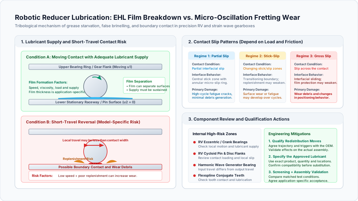
Robotic Reducer Lubrication and Micro-Oscillation Wear: How Sourcing Engineers Prevent Fretting Corrosion and EHL Breakdown in RV and Harmonic Drives
Review robotic reducer lubrication for RV and harmonic drives. Compare fretting risks, qualify grease and use an RFQ checklist to request a motion-profile review.
Robotic reducer lubrication needs application review when a joint repeatedly reverses over a small angle. Welding seam tracking, vision inspection, dispensing and wafer alignment can keep some contacts working over the same short track. Inadequate lubricant replenishment can then contribute to fretting wear, false brinelling and changes in positioning performance, even when catalog torque limits are respected.
The purchasing decision is to qualify the reducer, lubricant and motion profile together. Neither a grease consistency grade nor an output-angle limit establishes suitability on its own. This guide helps sourcing and mechanical engineers identify the vulnerable contact, request comparable test evidence and write an RFQ that exposes unresolved lubrication risks before production release.
Executive Sourcing & Tribology Summary
- Identify the contact: Output bearings, input bearings and tooth meshes experience different motion. A small joint stroke does not mean every internal bearing makes the same small stroke.
- Treat reversal as a risk condition: Low entrainment speed and poor replenishment can reduce film protection. Reversal alone does not prove that the entire oil film disappears.
- Approve the exact lubricant: Specify the manufacturer's product designation, quantity, application locations and replacement procedure. Chemistry families and NLGI grades are not interchangeable approvals.
- Separate screening from validation: An SRV grease test can compare friction and wear under stated conditions. It cannot certify complete reducer life or provide a universal robotic gearbox acceptance limit.
- Qualify redistribution moves: A larger movement may help lubricant circulation, but its trajectory, timing and effect need model-specific review and machine validation.
Published and last reviewed: November 12, 2026. Audience and region: Global sourcing, mechanical design and application engineering teams; English-language technical guidance. Scope: Housed strain wave (harmonic), cycloidal (RV) and precision planetary reducers under repeated reversal or dither. Limits: This is a sourcing framework, not a lubricant substitution approval, measured endurance study or service-life prediction. The numerical example below uses assumed inputs. Manufacturer instructions for the exact series, bearing arrangement and installation take precedence.
Evaluating a high-duty positioning axis? Submit the motion profile, loads, orientation and operating environment for an application review.
1. The Kinematics of Micro-Oscillation: Why EHL Protection Can Weaken
Elastohydrodynamic lubrication (EHL) describes fluid-film formation where contacting surfaces deform elastically under load. Surface motion draws lubricant into the contact, while viscosity, temperature, geometry and load influence film thickness. Continuous rotation can help distribute lubricant, but does not guarantee full-film separation.
Short repetitive movements may revisit the same loaded region without adequately replenishing it. At reversal, instantaneous entrainment speed falls, and steady-motion film calculations become less representative. Residual films, squeeze effects and boundary additives can still provide protection; it is inaccurate to assume completely dry contact at every reversal.
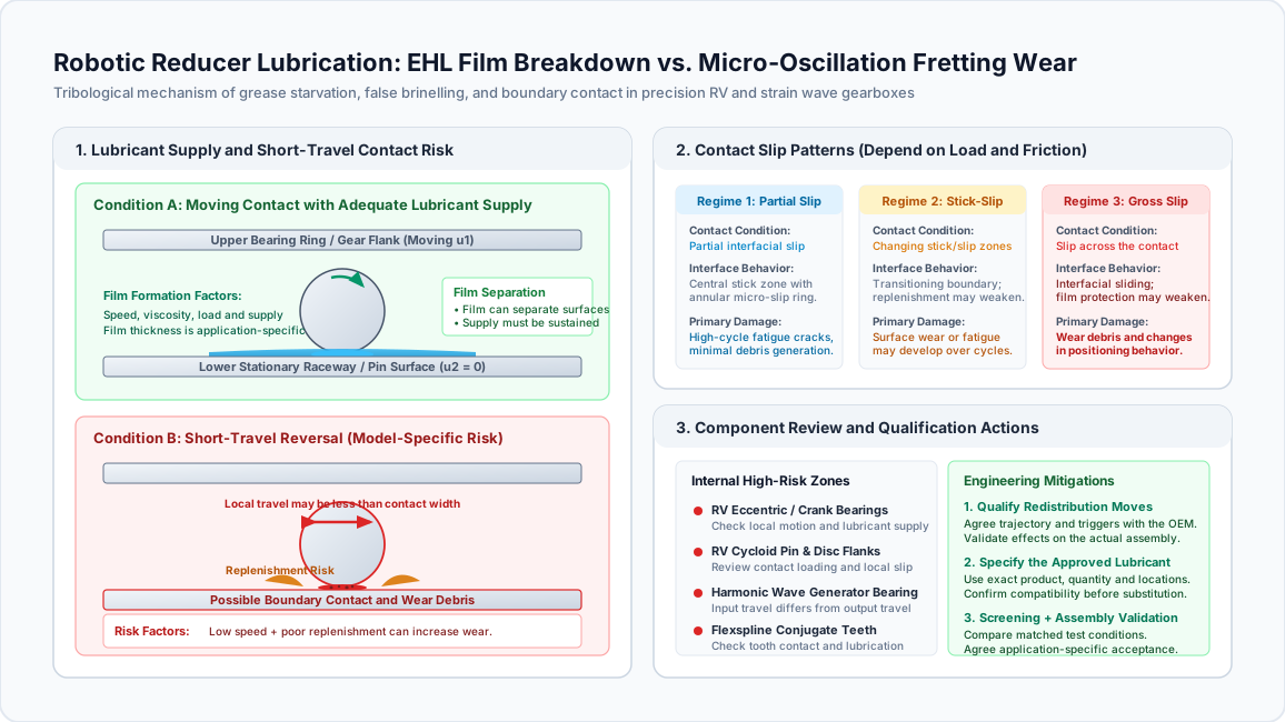
Conceptual schematic, not a measured contact image. Travel, film thickness and damage depend on the particular component, load, surface finish, lubricant and temperature. The diagram supplies no universal safe angle or lifetime.
1.1 Film-Thickness Models and Their Limits
Steady-state EHL models are useful for screening a defined contact. They require contact geometry, elastic properties, lubricant viscosity at operating temperature, pressure-viscosity behavior, load and entrainment speed. A point-contact equation cannot be applied unchanged to a line contact, and a fully flooded calculation can overstate protection when lubricant supply is restricted.
For purchasing, ask which model the supplier used and whether it accounts for the actual operating condition. A calculation at nominal running speed does not cover long dwell, repeated reversal or cold start. If those conditions dominate the application, request additional testing rather than accepting a calculated film thickness as an endurance guarantee.
1.2 The Lambda Ratio and Lubrication Regimes
The specific film thickness, often called the lambda ratio, compares estimated minimum film thickness with composite surface roughness:
lambda = h_min / sqrt(Rq1² + Rq2²)

h_min: estimated minimum lubricant film thickness
Rq1, Rq2: RMS roughness of the two contacting surfaces
Use the same length units for all three values.
Values around or above 3 are commonly used as a full-film screening indication; values around or below 1 suggest significant asperity interaction. These are approximate regime indicators. They do not describe additive chemistry, contamination or transient starvation, and they do not establish an allowable joint angle. A useful supplier calculation states both the roughness measurements and the viscosity temperature used.
1.3 Local Contact Travel Is Different from Joint Output Angle
For a point traveling around a pitch circle, the geometric arc length is:
S = pi × D × theta / 360

S: arc travel in mm
D: local pitch-circle diameter in mm
theta: full travel between reversal endpoints, in degrees
Illustrative calculation: Assume a local pitch diameter of 60 mm and a local travel of 0.2° between endpoints. Then S = pi × 60 × 0.2 / 360 = 0.105 mm. If a separately calculated contact width were 0.20 mm, the travel-to-width ratio would be about 0.52. That comparison identifies a contact worth reviewing; it does not predict wear or prove that fresh oil cannot enter it. Both geometry and contact width are assumed here, not measured reducer data.
Do not insert the robot's output angle into this calculation without establishing the internal kinematics. For an ideal fixed-ratio arrangement, a 0.4° output stroke at 100:1 corresponds to 40° of input travel. Cage motion and roller motion relative to each raceway require further analysis. Consequently, one output-angle threshold cannot describe all internal contacts.
A concrete manufacturer warning does exist: Harmonic Drive's reducer catalog, printed page 33 flags oscillation below 5° in its cross-roller-bearing life discussion because lubricant may not circulate adequately. Use the angle definition in that section and request application advice. It is not a universal failure boundary for wave-generator bearings, gear teeth or all brands of strain wave reducer.
2. Damage Mechanics: True Brinelling, False Brinelling and Fretting Corrosion
Returned units need a documented failure analysis. A stain or a change in positioning accuracy alone cannot identify which contact failed. Preserve the lubricant, photograph loaded regions before cleaning and record shipping, storage, shock and operating history.
2.1 True Brinelling: Plastic Indentation
True brinelling describes permanent contact indentations associated with excessive static or impact loading. Possible contributors include assembly damage, transport shock and collision loads. Inspect indentation shape and surface texture together with load records. There is no single contact-pressure limit that applies to all bearing materials, hardness levels and geometries.
2.2 False Brinelling: Wear at Repeated Contact Positions
False brinelling produces wear depressions at rolling-element positions during small relative movements, including vibration while a machine is idle or in transport. Material removal distinguishes it from a purely plastic indentation. Surface appearance can vary with lubrication and oxidation, so polished or discolored tracks require microscopic examination rather than an immediate diagnosis from color.
2.3 Fretting Corrosion: Small-Motion Wear with Oxidation
Repeated small relative movement can disrupt protective films, generate wear particles and permit oxidation. Reddish-brown debris, sometimes called “cocoa,” is a warning sign on steel contacts, but lubricant color cannot establish the oxide species or exclude water contamination and ordinary rust. Ask for debris microscopy or composition analysis when the distinction affects corrective action.
Record backlash or lost motion under the same torque, temperature and measurement procedure before comparing results. A change can also arise from preload, assembly or structural compliance. Neither visible debris nor a larger position error justifies assigning a universal remaining life.
3. Reducer Architectural Vulnerability: RV Cycloidal vs. Harmonic Strain Wave
Architecture helps locate review points; it does not rank fretting resistance by itself. Compare candidate units at the required load, mounting arrangement, stroke and temperature, including bearings supplied outside the reducer.
3.1 Cycloidal (RV) Reducers
Review eccentric or crankshaft bearings, cycloidal disc and pin contacts, and the main output bearing. Their local speeds and reversal patterns differ. A short output movement can still produce substantial input-side movement, while the output bearing repeatedly carries the same external moment zone.
Ask the supplier to identify the installed bearing types, lubricant path and service access. Do not assume every RV reducer uses needle bearings or a cross-roller output bearing. Housing orientation can change lubricant distribution, and the approved fill instruction should specify quantity and location rather than an unsupported percentage of the entire cavity.
3.2 Strain Wave (Harmonic) Reducers
Review the wave-generator bearing, flexspline/circular-spline mesh and output support bearing separately. Thin flexible components, tooth engagement and bearing motion create different validation needs. An output-bearing oscillation warning does not automatically describe the input bearing's travel.
Component sets and housed units can also arrive in different lubrication states. Confirm what is factory lubricated and what the assembler must apply. Harmonic Drive's lubrication guidance on printed pages 16–17 differentiates products and relates grease replacement to temperature and loading. Do not transfer a grease designation or maintenance interval to a different series without approval.
4. Grease Chemistry: Selecting an Approved Lubricant
Specify the exact approved lubricant first, then use its technical data to explain suitability. A supplier's claim that a grease is “synthetic,” “robot grade” or “high EP” does not establish compatibility with the reducer.
4.1 Base Oil: Viscosity at the Actual Temperature
Ask for viscosity data and the approved operating envelope. Higher viscosity can support film formation while increasing cold-start drag; lower viscosity may improve mobility while changing film thickness. There is no universal optimal viscosity band for RV and strain wave reducers. Bulk temperature, speed and contact loading must accompany any viscosity comparison.
4.2 Thickener: Consistency Is Only One Property
NLGI grade describes grease consistency, not base-oil viscosity or fretting performance. Lithium, urea and other thickener systems require formulation-specific evidence. A softer grease can redistribute differently, but may also leak more readily in a particular enclosure. Conversely, NLGI 2 is not inherently unsuitable for precision reducers: the Harmonic Drive catalog's grease specification table on page 16 includes that grade.
4.3 Additives, Mixing and Seals
Anti-wear and extreme-pressure additives can help protect boundary contacts, but their presence does not approve a substitute. Request compatibility evidence for metals, coatings, seals and the existing grease. Avoid blanket requirements for a particular molybdenum compound, thickener or seal elastomer unless the manufacturer specifies it.
If a change is proposed, document the old and new products, cleaning or purge procedure, residual mixing allowance and approval owner. Similar color or consistency is not evidence that two greases can be mixed.
5. Comparative Matrix: Lubricant Decisions and Evidence
These six rows are procurement decisions, not a performance ranking of chemistry families. No row authorizes substitution without the reducer manufacturer's approval.
| Lubricant decision | Potential benefit | Risk to resolve | Evidence to request |
|---|---|---|---|
| Retain the specified factory grease | Preserves the documented baseline | Application may exceed its approved duty | Exact designation, manual revision and duty approval |
| Change base-oil viscosity | May alter film formation and cold-start behavior | Higher drag or inadequate film protection | Viscosity-temperature data and application test |
| Change NLGI consistency | May alter distribution and retention | Leakage, churning or poor replenishment | Model-specific fill and torque/leakage results |
| Change thickener or additive package | May improve a demonstrated weakness | Mixing, material and seal incompatibility | Compatibility assessment and controlled comparison |
| Use a cleanroom or vacuum lubricant | May address process contamination constraints | Wear, torque and outgassing remain separate requirements | Process-specific contamination data and reducer approval |
| Adopt an alternate supply product | May reduce supply interruption | Similar labels can hide different formulations | Written substitution approval and traceable product specification |
6. Component Vulnerability Matrix: What to Ask the Supplier
Use the actual assembly drawing to confirm whether each subassembly is present. Ask the supplier to distinguish output stroke, input stroke and local contact travel in every explanation.
| Subassembly | Architecture | Potential concern under repeated reversal | Engineering and procurement action |
|---|---|---|---|
| Eccentric/crankshaft bearings | Cycloidal, where fitted | Local wear or inadequate replenishment | Obtain bearing arrangement and local-motion assessment |
| Cycloidal discs and pins | Cycloidal | Repeated loaded tracks and debris | Review lubrication path and inspect after endurance testing |
| Main output support bearing | Housed RV or strain wave | Small-angle raceway wear under external moment | Check oscillation guidance, preload and moment spectrum |
| Wave-generator bearing | Strain wave | Lubricant distribution and bearing wear | Review input motion and approved grease application |
| Flexspline/circular-spline teeth | Strain wave | Flank wear and changing transmission behavior | Agree inspection and lost-motion measurement procedures |
| Sun/planet gear contacts | Precision planetary | Reversal wear and backlash growth | Review tooth loading, lubrication and bidirectional endurance |
7. Tribological Tests and Application Acceptance Criteria
A test method defines how to obtain a result; it does not automatically supply a pass/fail limit for robotic reducers. The official scopes of ASTM D7594-19 and ASTM D5707-19 describe grease screening under oscillatory contact and call for assessing correlation with the application. These linked editions are historical references; agree the applicable revision with the laboratory before ordering a test.
Ask for the complete report, including specimens, load, stroke definition, frequency, temperature, duration, lubricant conditioning, repeat count and measurement uncertainty. A wear-scar value from one setup cannot be compared fairly with a value from another setup. Modified conditions must be labeled and cannot inherit a standard's stated precision without justification.
| Test or qualification step | What it addresses | Required report detail | How to set acceptance |
|---|---|---|---|
| ASTM D7594 SRV screening | Grease behavior under short-stroke fretting conditions | Edition, specimens, conditions, friction and wear results | Compare with an approved baseline; agree application correlation |
| ASTM D5707 SRV screening | Friction and wear under linear oscillation | Edition, temperature, load, stroke and friction history | Use matched conditions; avoid a universal friction cutoff |
| Grease compatibility assessment | Proposed product change or residual mixing | Mixing proportions, conditioning and measured changes | Use manufacturer-approved transition requirements |
| Orientation and sealing trial | Retention, leakage and distribution in the assembly | Fill quantity, mounting attitude, temperature and leakage | Agree functional and contamination limits |
| Complete reducer endurance test | Behavior under the intended motion and load | Cycle history, temperature, torque and inspection records | Define permissible performance drift before testing |
| Post-test lubricant and surface analysis | Debris and possible damage mechanisms | Sample locations, microscopy and lubricant condition | Compare with baseline and the documented rejection criteria |
A bench grease test cannot establish collision tolerance or whole-gearbox life. An endurance run also needs a justified acceleration method before its duration can be translated into a service-life claim.
8. Sourcing and Engineering RFQ Checklist
Include this checklist in the application data sheet and require a named approval owner for every unresolved item:
- 1. Motion profile: Provide endpoint-to-endpoint output travel, ratio, waveform, frequency, dwell and cycles per day; state whether any quoted amplitude is half-stroke.
- 2. Load spectrum: Include torque reversals, external radial/axial loads, overturning moment and expected shock events.
- 3. Contact review: Ask which bearings or meshes need special small-angle consideration and which manual definitions apply.
- 4. Factory lubricant: Record exact product designation, approved alternatives, shelf life and traceability requirements.
- 5. Fill instruction: Specify mass or volume, application locations, installation orientation and assembly sequence from the applicable manual.
- 6. Compatibility: Confirm seals, metals, coatings and any remaining lubricant are compatible with the proposed fill.
- 7. Test evidence: Request matched-condition screening reports and identify how they relate to this reducer and duty.
- 8. Maintenance: Agree inspection, sampling and replacement instructions, including access or factory-service requirements.
- 9. Redistribution motion: Obtain approval for any proposed sweep and document process, clearance and controller constraints.
- 10. Production release: Agree the endurance profile, measurement method, allowable drift and written application approval before purchase release.
Use the Gearbox Sizing and Service Factor Calculator for preliminary load screening. It does not evaluate EHL film formation, grease suitability or fretting life. Compare RV Speed Reducers and Harmonic Drive Reducers, then send the completed duty profile for review.
9. Engineering and Control Countermeasures: Qualify a Redistribution Move
Where the process permits, a larger movement can be considered to redistribute lubricant and vary the repeatedly loaded track. There is no universal sweep angle, speed or interval for all reducers. A joint move also does not guarantee that fresh lubricant reaches every internal contact.
Record the actual dither and load profile
                  |
                  v
Manufacturer reviews contacts and lubricant distribution
                  |
                  v
Is an additional movement permitted and useful?
       | Yes                         | No
       v                             v
Define trajectory and triggers   Review alternative reducer,
with machine integration team    lubricant system or process
       |
       v
Validate temperature, torque, leakage and wear
       |
       v
Release only the approved controller settings
9.1 Sweeping Kinematic Rules
Define the proposed motion in the same coordinate system as the manufacturer's requirement. Record acceleration, peak speed, payload, orientation and the operating condition that triggers it. Choose an available process window and validate the full machine trajectory, including tooling, cables and workholding.
If the move is omitted or fails, the controller response should follow the agreed machine and maintenance procedure. Do not reset a counter and assume lubrication has been restored. Compare endurance results with and without the proposed move under otherwise matched conditions. This article provides no measured lifetime improvement from sweeping and makes no warranty claim based on its use.
10. Frequently Asked Questions (FAQ)
Can we substitute standard industrial EP2 lithium grease if factory robot grease is out of stock?
Only with written approval for the exact replacement product and application. “EP2” does not establish equivalent base oil, additives, compatibility or wear performance. NLGI 2 itself is not a disqualifier; some manufacturer-specified reducer greases use that consistency. Ask for an approved alternative or a controlled transition plan instead of selecting by label.
Why do some robotic gearboxes leak liquid oil even though they were filled with grease?
Grease can release base oil. Leakage can also involve fill quantity, orientation, pressure, temperature, seal condition or installation. Inspect the actual unit and compare the fill with its instruction. A small amount of oil at a seal does not prove thickener failure, and changing to a different seal material is not an automatic repair.
What is the tell-tale sign of fretting corrosion during gearbox inspection?
Repeated wear tracks and oxidized debris can suggest fretting, but color alone is insufficient. Record the track locations, preserve lubricant samples and distinguish wear from overload indentation and water-related corrosion. Microscopy and debris analysis help determine whether the proposed lubricant or motion change addresses the actual mechanism.
Does an RV reducer have better micro-oscillation resistance than a harmonic drive?
There is no universal ranking. Bearing arrangement, external moment, lubricant supply, ratio and local contact movement can matter more than the architecture label. Compare candidate assemblies with the same duty profile and acceptance procedure. A higher catalog torque rating does not establish better fretting performance.
How does operating temperature influence micro-oscillation wear?
Temperature changes viscosity, grease mobility and lubricant aging, while cold starts can increase resistance to motion. Measure housing temperature and establish how it relates to the supplier's lubricant temperature limit. Use the model's approved ambient and housing limits; this guide does not prescribe a universal temperature window.
What is the difference between NLGI 00, NLGI 0 and NLGI 2 greases in robotic joints?
They describe increasingly firm grease consistency. They do not specify the base-oil viscosity, chemical compatibility or endurance capability. The appropriate grade depends on the reducer's design and approved product. Do not assume a softer grease will reach every contact or that a firmer grease will always cause starvation.
Can diamond-like carbon coatings eliminate the need for specialized grease?
A coating can change contact behavior, but cannot establish lubricant-free operation without design-specific evidence. Coating adhesion, contact stress and compatibility still require validation. Treat a coated variant as a changed assembly requiring approval rather than a reason to omit the specified lubricant.
How often should grease be replaced under micro-dither?
Follow the model-specific instruction and obtain an application adjustment where required. Consider temperature, load, cumulative operation, contamination and condition trends. Agree sample locations and alarm criteria with the supplier; a universal operating-hour interval or iron concentration limit would not account for different materials, grease fills and sampling methods.
11. Next Steps for a Reliable Sourcing Decision
Before releasing a reducer for production, collect four items: a defined motion and load spectrum, an approved lubrication instruction, a comparable validation report and written application acceptance. An unresolved item should remain visible in the RFQ rather than being replaced with a generic grease specification.
Start by identifying the contact that sees repeated short travel. Then ask whether the proposed lubricant and installation support it, and whether the evidence represents that duty. If uncertainty remains, use a pilot assembly and an agreed inspection plan before committing to a fleet-wide change.
Contact Robotized Gearbox application engineers with the reducer model, ratio, motion trace, loads, temperature and mounting orientation. You can also review RV Speed Reducers and Strain Wave Reducers to prepare the candidate list for that discussion.
Sources / References
Source review: November 12, 2026. The manufacturer catalog and test-method scopes below support the explicitly attributed guidance. Decision tables and the assumed calculation are editorial sourcing tools, not manufacturer test results. Verify current revisions during formal qualification.
- Harmonic Drive LLC: Reducer catalog — engineering data. Printed pages 16–17 cover lubricant selection and grease life; page 33 discusses small-angle oscillation of the cross-roller bearing. These sections do not establish a common threshold for all reducer contacts.
- ASTM International: ASTM D7594-19 — SRV fretting-wear test for lubricating greases. Historical test-method scope; relevant to short-stroke grease screening, not a complete robotic reducer certification or universal wear-scar acceptance limit.
- ASTM International: ASTM D5707-19 — SRV friction and wear test for lubricating grease. Historical test-method scope; comparisons require stated, matched conditions and application correlation. Confirm the applicable revision before testing.
- Nabtesco Corporation: Precision Equipment regional contact directory. Use this manufacturer directory to request the exact RV model's installation and lubrication documents. It is a navigation resource, not evidence for a 10° operating limit, grease formulation or replacement interval.
Author

Categories
More Posts
Preventing Thermal Failure in AGV and AMR Drive Gearboxes: A Sourcing Guide
Why compact AGV wheel gearboxes fail from heat before they fail from load, and how procurement and engineering teams can specify thermal limits correctly.
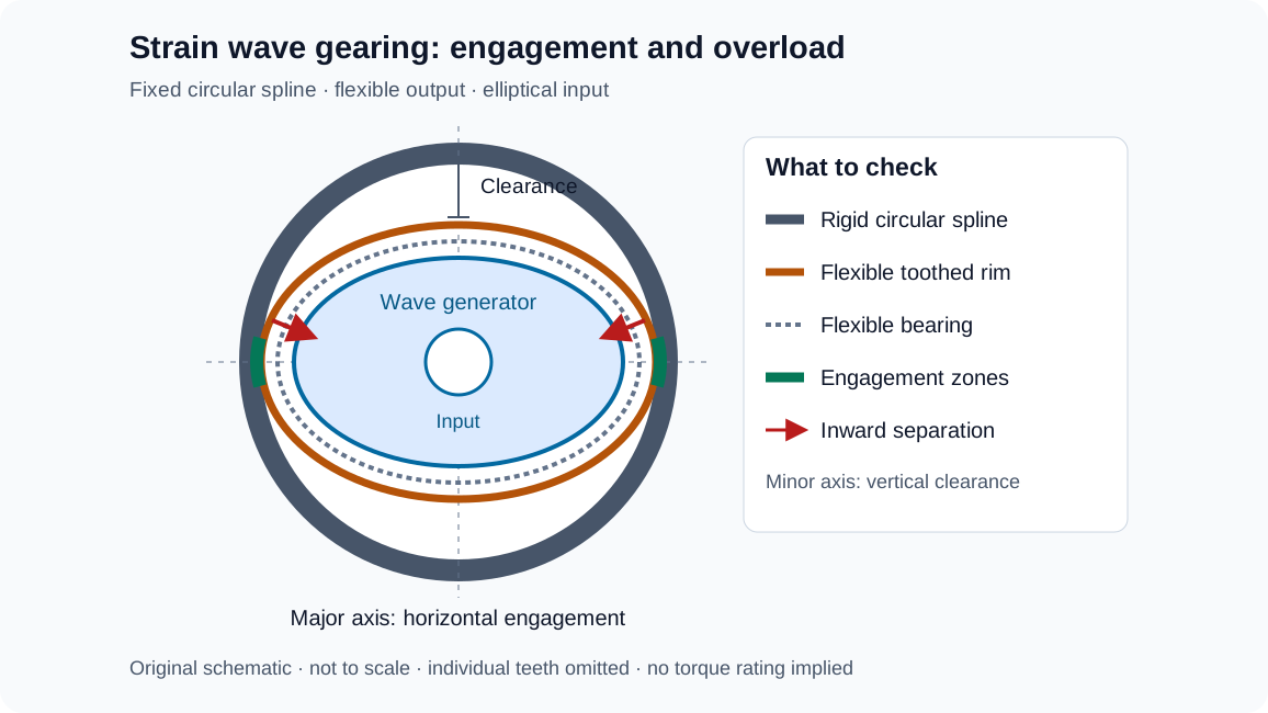
Harmonic Drive Ratcheting and Flexspline Fatigue: How Sourcing Engineers Size Strain Wave Reducers for Peak Torque and Lifespan
Review harmonic drive ratcheting, flexspline fatigue, peak torque limits, and bearing-life calculations. Prepare a strain wave reducer RFQ with our checklist.
Specifying Gearboxes for High-Payload Cobots: Why 20kg+ Arms Require Cycloidal Drives
Learn how to specify high-payload cobot gearboxes for 20kg+ arms: harmonic vs cycloidal tradeoffs, joint architecture, RFQ checks, and supplier evidence.