
Harmonic Drive Ratcheting and Flexspline Fatigue: How Sourcing Engineers Size Strain Wave Reducers for Peak Torque and Lifespan
Review harmonic drive ratcheting, flexspline fatigue, peak torque limits, and bearing-life calculations. Prepare a strain wave reducer RFQ with our checklist.
Harmonic drive ratcheting occurs when excessive torque makes the flexspline teeth lose correct engagement with the circular spline and skip. It can damage the teeth, lower the subsequent ratcheting threshold, and leave the gear engaged eccentrically. Flexspline fatigue is a different problem: repeated deformation can initiate cracks in the flexible gear body. A reducer must pass both overload screening and duty-cycle life checks.
For motion control engineers and procurement managers sourcing compact robot joint reducers, continuous rated torque alone cannot establish suitability. Normal acceleration, emergency braking, input speed, mounting stiffness, and lubrication each impose separate constraints. A bearing-life estimate also cannot approve a collision load.
This guide provides a torque acceptance matrix, a reproducible bearing-life calculation, and an RFQ checklist for comparing strain wave reducer offers. It is a document-based selection guide; the example is hypothetical and does not represent a physical endurance test or a certified product rating.
Executive Sourcing Summary
- Screen overloads separately: Compare normal acceleration with repeated peak torque and abnormal stops with momentary peak torque. Ratcheting and buckling thresholds are damage boundaries, not operating allowances.
- Keep life definitions consistent: State whether a supplier quotes L10 or L50, which speeds and loads define the rating, and whether the requirement uses motion hours or complete machine-cycle hours.
- Request exact model evidence: Frame size and reduction ratio do not establish cross-brand equivalence. Obtain the selected part number, catalog revision, mounting conditions, and application approval.
- Treat unknowns as open items: Missing shock-load data, lubricant approval, or output-bearing capacity cannot be replaced by a generic service factor.
Published and last reviewed: November 6, 2026. Scope: Global sourcing and preliminary mechanical sizing of strain wave component sets and housed reducers for robot joints and precision positioning. Limits: This guide does not validate medical use, robot safety functions, or supplier manufacturing capability. Final selection requires the manufacturer's model-specific ratings and an application review. Recheck these references when a supplier changes the product revision or operating conditions.
Evaluating a joint reducer? Submit your load profile, stop estimates, and mounting drawing for an engineering sizing review.
1. Kinematics of Strain Wave Gearing: The 3 Core Elements
The standard arrangement uses three elements:
- Wave generator: An elliptical cam and flexible bearing driven by the motor. It imposes the changing shape that moves the tooth engagement zones.
- Flexspline: A flexible toothed cup or other thin-walled gear form. In the arrangement discussed here, it supplies the reduced-speed output.
- Circular spline: A rigid internal gear fixed to the housing. A common design has two more teeth than the flexspline.
For that fixed-circular-spline arrangement, the signed input-to-output speed ratio is:
i = input speed / output speed
  = -Z_FS / (Z_CS - Z_FS)

If Z_CS - Z_FS = 2, then i = -Z_FS / 2.
Here, Z_FS and Z_CS are the respective tooth counts. The negative sign indicates opposite input and output directions. Changing which element is fixed changes the kinematic relationship; verify the actual assembly rather than applying this formula to every strain wave configuration.
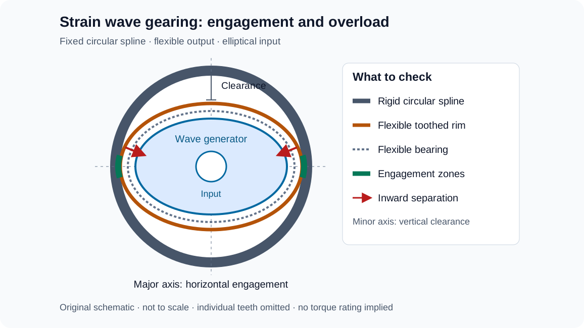
The flexspline meshes with the circular spline near the ellipse's major axis and clears it near the minor axis. As the wave generator rotates, these engagement regions travel around the circumference. The tooth-count difference produces the small relative output movement. The Harmonic Drive LLC reducer catalog, engineering data illustrates the common configurations.
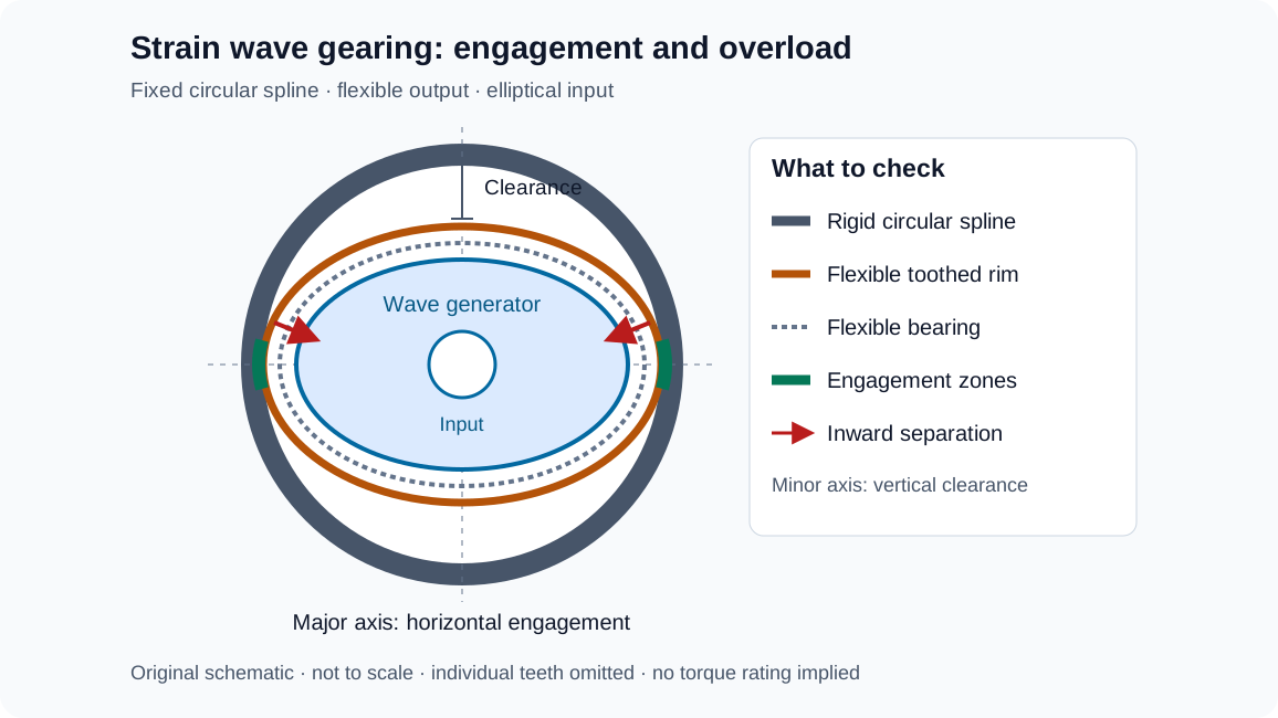
Original explanatory schematic, not to scale. The drawing omits individual teeth and bearing balls; it is not a manufacturing drawing or a measured contact pattern.
Multi-tooth engagement helps distribute load, but its extent depends on tooth geometry, deformation, and operating load. A universal percentage of engaged teeth is not a reliable procurement specification. Ask for transmission error, lost motion, stiffness, and load ratings under stated test conditions instead.
2. Ratcheting Torque vs. Momentary Peak Limits
Catalogs describe several distinct torque limits. Their symbols and definitions vary between manufacturers, so copy the definitions into the comparison sheet before comparing values.
The Operational Torque Checks
- Rated torque, T_N: A reference continuous output load at a stated input speed. It is also an input to the supplier's bearing-life model.
- Limit for average torque: The allowable equivalent duty-cycle load. Some catalogs list it separately from rated torque; do not silently substitute one for the other.
- Repeated peak torque, T_R: The ceiling for normal acceleration and deceleration peaks. Passing the average-load calculation does not excuse exceeding this ceiling.
- Momentary peak torque, T_M: A limit for abnormal loads such as collisions or emergency braking, subject to the manufacturer's duration and occurrence rules.
- Ratcheting torque, T_ratchet: The threshold for tooth skipping under the specified test and mounting conditions. It is not an extra operating reserve above T_M.
- Buckling torque, T_B: A structural damage threshold associated with plastic deformation of the flexspline. It is not a fatigue rating.
Use independent checks rather than a chain of inequalities implying that every actual stop must exceed every acceleration peak:
Equivalent torque <= catalog limit for average torque
Normal acceleration/deceleration peak <= repeated peak limit
Abnormal stop torque <= momentary peak limit
Maximum and average input speeds <= their respective limits
Calculated rating life >= required life, using the same life basis
The housing matters. A circular spline supported by a compliant customer housing can behave differently from the catalog test assembly. The Harmonic Drive SE mechatronics catalog, ratcheting definition treats ratcheting as an overload phenomenon and directs buyers to request the applicable threshold. Do not extrapolate a universal multiplier from another reducer series.
The Mechanics of Ratcheting and the Dedoidal State
Under excessive transmitted torque, tooth forces and elastic deformation can reduce effective engagement until the teeth skip. This can create wear and asymmetric mesh. Manufacturers call an eccentric engagement condition dedoidal; it can also result from incorrect assembly, so it is not proof of a particular collision history or a description of an inevitably three-lobed plastic shape.
After a Collision or Suspected Tooth Skip
Stop operation and secure the axis according to the machine's maintenance procedure. Record the event, motor-current changes, vibration, and any increase in lost motion. Seek the reducer supplier's inspection and disposition instructions before returning the axis to service. Software offset correction cannot establish mechanical integrity, and symptoms alone do not establish the failure mode.
3. Structural Torque and Failure Mode Acceptance Matrix
Use this matrix to compare quotations without inventing ratings for a generic frame size. Each row represents a separate acceptance question. An empty field means the selection remains open, even if another vendor lists a larger headline torque number.
| Selection check | Application input | Supplier evidence needed | Hold point before approval |
|---|---|---|---|
| Rated conditions | Output torque and input speed | Rated torque at the stated reference speed | Rating conditions do not match the calculation |
| Equivalent duty load | Torque, absolute speed, and duration for each segment | Limit for average torque and calculation method | Average-load definition is unclear |
| Repeated peaks | Acceleration and braking peaks in every normal cycle | Repeated peak limit for the exact model | A normal-cycle peak exceeds the limit |
| Abnormal stops | Stop torque trace, duration, and expected frequency | Momentary peak limit and cumulative exposure rule | Stop severity or duration is unknown |
| Tooth skipping | Shock load plus housing and mounting stiffness | Ratcheting threshold with boundary conditions, if available | Threshold is inferred from another brand |
| Structural overload | Static jam and locked-axis loads | Manufacturer review of structural limits | Buckling torque is being used as allowable load |
| Bearing fatigue | Full load/speed history and required hours | L10 or L50 baseline, reference speed, and life calculation | The offer compares different life definitions |
| Output support | Radial, axial, and overturning moment loads | Output-bearing static and dynamic load review | External moments are checked only against gear torque |
These are document acceptance checks, not replacement torque specifications. For component sets, also identify which party designs and validates the input support, housing, and output bearings. A component-set quotation and a housed-unit quotation may allocate those responsibilities differently.
4. Why Reduction Ratio Alone Cannot Predict Ratcheting Vulnerability
Lower ratios can be attractive when output speed matters, while higher ratios can reduce the ideal motor torque needed to generate a given output torque. For a fixed target output speed, increasing the ratio increases input speed. This can change losses and bearing life even if the output torque remains unchanged.
Tooth count, profile, cup geometry, and housing support all affect the overload boundary. There is no general rule that ratcheting resistance increases exponentially or monotonically with reduction ratio. Compare the exact catalog rows rather than assuming that a 160:1 unit survives a collision better than an 80:1 unit.
| Ratio decision | Engineering question | Evidence to compare |
|---|---|---|
| Output speed | Can the joint complete the motion within the cycle time? | Motor speed and maximum input-speed limit |
| Continuous duty | Does the selected ratio create excessive average input speed? | Full-cycle speed calculation and thermal assessment |
| Acceleration | What motor and load inertia must be accelerated? | Consistent reflected-inertia and torque model |
| Tooth skipping | What overload can this exact assembly tolerate? | Model-specific ratcheting information |
| Positioning | Does compliance meet settling and accuracy requirements? | Hysteresis, stiffness, and transmission-error records |
| Installation | Does the ratio option use the same interfaces and supports? | Approved drawing and assembly instructions |
For sourcing, specify the required output motion first, then compare motor/reducer combinations against the same duty cycle. A different ratio is an engineering change that may require control retuning, thermal confirmation, and renewed stop-load analysis.
5. Flexspline Fatigue Life: What the Calculation Can Establish
The flexspline repeatedly changes shape as the wave generator rotates. In the conventional two-lobe arrangement, a material location experiences approximately two bending cycles per relative wave-generator revolution. This deformation acts alongside transmitted torsion, local tooth contact loading, and assembly-induced stresses.
A single shell-bending expression cannot predict cup life. A useful stress analysis must account for the change in curvature from the original shape, wall-thickness distribution, tooth-root geometry, diaphragm transitions, material condition, residual stresses, and the actual support constraints. A static equivalent-stress value also cannot be compared directly with an endurance limit to establish life without a fatigue method that treats stress amplitude, mean stress, and load history.
The practical procurement distinction is between an approved operating envelope and demonstrated endurance. A manufacturer may rate the flexspline for fatigue endurance within its specified repeated-load envelope. That does not mean every housing, overload, or assembly error preserves that rating. Conversely, a bearing-life calculation is not a separate flexspline stress calculation.
Sourcing Quality Differentiator: Traceable Process Evidence
Ask the supplier how it controls material cleanliness, heat treatment, wall geometry, surface condition, and final inspection. Request records tied to the quoted part number and production lot. Do not prescribe a steel grade, remelting process, inclusion rating, or peening stress merely because another brand uses it; those choices form part of a validated component design.
For an endurance report, require the tested model and ratio, sample count, load waveform, input speed, temperature, lubricant, mounting arrangement, run duration, and failure criteria. An undamaged sample at the end of a short test does not establish a fleet-wide service-life guarantee. Likewise, a country-of-origin label or a dimensional interchangeability claim cannot establish fatigue parity.
Where the supplier cannot release detailed stress models, seek a signed application review and relevant endurance evidence. Record the limitation rather than filling the missing data with an unsupported lifespan estimate.
6. Wave Generator Bearing Fatigue Life Modeling
The flexible wave-generator bearing can govern catalog rating life even when the gear teeth remain serviceable. Use the reducer manufacturer's model: a conventional bearing equation with output torque substituted for bearing load is not independently valid.
A common manufacturer relationship is:
L_h = L_n * (T_r / T_av)^3 * (N_r / N_av)Here L_n is the catalog baseline life, T_r and N_r are its reference torque and input speed, and T_av and N_av describe the application. The Harmonic Drive LLC catalog, page 12 distinguishes L10 and L50 baselines for its listed series. These baselines must not be assigned automatically to another manufacturer's product.
L10 is a statistical rating associated with 90% survival against the defined bearing fatigue mechanism under the calculation conditions. It is not a scheduled failure time, a warranty, or the reliability of an entire robot joint. The SKF rolling-bearing catalog, printed page 89 explains this distinction and the influence of lubrication, contamination, and mounting.
Calculating Equivalent Torque and Mean Speed
For piecewise constant segments, use torque magnitudes and absolute input speeds. Direction reversals must not cancel bearing exposure:
T_av = [sum(|n_i| * t_i * |T_i|^3) / sum(|n_i| * t_i)]^(1/3)
N_av = sum(|n_i| * t_i) / sum(t_i)
Use the same time window for N_av and the reported life hours. If the denominator includes dwell, the result uses complete cycle hours. If it excludes dwell, the result uses motion hours. A zero-speed segment contributes no revolutions in this model, but static holding torque, fretting, oscillatory motion, and restart lubrication require separate checks. An all-stationary profile cannot be evaluated by dividing by zero in this formula.
Worked Example: Dwell Changes the Hour Basis
The following hypothetical candidate has an assumed L10 baseline of 10,000 hours at T_r = 40 Nm and N_r = 2,000 rpm. These are calculation inputs, not a rating for a named size or product series. Each listed speed is a representative segment value; integrate a real varying-speed trace rather than blindly averaging a ramp.
| Segment | Absolute input speed (rpm) | Duration (s) | Output torque magnitude (Nm) |
|---|---|---|---|
| Acceleration segment | 1,500 | 0.4 | 65 |
| Process traverse | 2,400 | 1.2 | 28 |
| Braking segment | 1,200 | 0.4 | 50 |
| Dwell | 0 | 1.0 | 0 |
Speed-time sum = 1500*0.4 + 2400*1.2 + 1200*0.4 = 3960 rpm*s
Cubic load sum = 600*65^3 + 2880*28^3 + 480*50^3
               = 287,996,760 rpm*s*Nm^3

T_av = (287,996,760 / 3960)^(1/3) = 41.741 Nm
N_av, complete cycle = 3960 / 3.0 = 1320 rpm
L10h, complete cycle = 10,000 * (40 / 41.741)^3 * (2000 / 1320)
                    = approximately 13,333 complete cycle hours

N_av, moving segments = 3960 / 2.0 = 1980 rpm
L10h, motion basis = approximately 8,889 motion hours
Both hour figures describe the same assumed revolution exposure: the machine spends two-thirds of this cycle moving. This conversion does not prove that dwell is harmless or approve any of the instantaneous loads.
If the requirement is 20,000 complete cycle hours on an L10 basis, this candidate does not meet that numerical screening target. Request another candidate, reduce the load/speed exposure, or revise the motion profile and repeat the supplier's calculation. A specific larger frame size or a different steel grade cannot be declared sufficient from this example alone.
The cubic relationship also makes torque uncertainty consequential. At unchanged speed and reference conditions, increasing equivalent torque by 25% multiplies calculated life by approximately 0.512. This is a model sensitivity, not permission to operate above the catalog's average or peak limits. A sourcing comparison should show both the life estimate and every independent limit check.
7. Lubrication and Thermal Limits
Lubrication affects tooth wear, bearing operation, leakage, starting torque, and achievable service intervals. The approved lubricant depends on the selected reducer, size, ratio, orientation, sealing, and environment. A grease supplier's temperature range does not by itself establish the gearbox's operating range.
The manufacturer catalog separates lubricant compatibility, fill and application instructions, temperature effects, and service guidance. See Harmonic Drive LLC lubrication guidance, pages 16–19. Avoid converting that guidance into one universal fill percentage or a fixed replacement interval for all strain wave reducers.
| Lubrication decision | Required RFQ information | Selection limitation |
|---|---|---|
| Factory lubricant | Exact approved designation and supplied condition | A component set may require lubrication during assembly |
| Fill quantity | Quantity and application locations for this model | Overfilling can increase losses and heat |
| Temperature | Ambient, internal or housing measurement point, and duty | State which temperature a published limit describes |
| Orientation | Wave-generator position and required sealing | Horizontal assembly guidance may not apply vertically |
| Maintenance | Supplier interval and its load/speed/temperature assumptions | Bearing rating life is not lubricant life |
| Special environment | Vacuum, cleanliness, food-contact, or material requirements | A specialty grease needs reducer and seal compatibility approval |
Vertical Mounting and Grease Changes
Provide the installed orientation and ask for the applicable lubricant quantity, sealing arrangement, and maintenance instructions. Obtain written approval before substituting or mixing lubricants. Do not prescribe extra packing or a particular seal design without confirming its effect on heat, drag, and lubricant delivery.
For sample validation, agree on the measurement location, ambient temperature, load sequence, speed, warm-up period, and allowable stabilized temperature. Compare those conditions with the application. A short no-load spin test cannot establish thermal suitability at production duty.
8. Procurement and Engineering RFQ Checklist
Use one common input package for all suppliers so their offers can be compared on the same basis:
- 1. Model identity: Record manufacturer, complete part number, ratio, drawing revision, and whether the offer is a component set or a housed unit.
- 2. Duty trace: Supply signed output torque, input speed, segment times, direction changes, dwell, and annual operating hours; identify measured values and estimates.
- 3. Torque limits: Obtain rated, average, repeated peak, and momentary peak definitions and values. Request ratcheting information with housing conditions where available.
- 4. Stop exposure: Give the abnormal stop torque, duration, speed during braking, and expected lifetime count. Request the supplier's cumulative exposure assessment.
- 5. Bearing-life basis: State L10 or L50, reference conditions, required hours, and whether those hours include dwell. Keep lubricant life separate.
- 6. Flexspline quality: Request material and process traceability, inspection criteria, and relevant endurance evidence without asserting unverified metallurgy requirements.
- 7. Output support: Supply radial and axial forces, overturning moment, lever arms, and load direction; obtain separate static and dynamic bearing checks.
- 8. Precision acceptance: Agree on lost motion, hysteresis, stiffness, transmission error, runout, test load, temperature, and measurement method.
- 9. Installation and lubricant: Confirm housing tolerances, bolt tightening, assembly sequence, approved lubricant, quantity, orientation, and maintenance access.
- 10. Release documents: Request an application review, sample acceptance plan, lot inspection report, and a process for notifying buyers of design or material changes.
Use the Gearbox Sizing and Service Factor Calculator for preliminary service-factor screening. It does not replace the speed-weighted strain wave bearing-life calculation above. Review our Precision Harmonic Drive Reducers catalog to discuss configurations, or send the completed RFQ checklist for a model-specific review.
9. Frequently Asked Questions
What is the difference between ratcheting torque and buckling torque?
Ratcheting concerns loss of tooth engagement under overload. Buckling concerns structural deformation of the flexspline. Neither is an allowable operating torque. Their values and relationship depend on the selected reducer and boundary conditions; do not use a generic ratio between them to approve a design.
Can a strain wave gearbox recover after a single ratcheting event?
Do not assume normal motion means the unit is undamaged. Ratcheting can increase wear, reduce the subsequent threshold, or leave eccentric mesh. Remove the axis from operation for supplier-directed inspection and disposition. Replacement may be necessary; a blanket claim that every event produces the same irreversible damage is not a diagnosis.
Do low-ratio harmonic drives always ratchet more easily?
No universal ordering applies across products. Compare the exact size, ratio, tooth design, and mounting conditions. A ratio change also changes input speed for a given output motion, so check bearing life, peak speed, motor matching, and heat alongside overload capability.
How does ambient temperature affect wave-generator bearing life?
Temperature changes lubricant viscosity and can accelerate degradation, affecting the conditions behind a rating-life estimate. The effect depends on the lubricant, internal temperature, duty, and contamination. There is no universal percentage life loss for a given temperature rise. Request the supplier's temperature limits and confirm them at an agreed measurement point.
What causes a flexspline cup to crack near the diaphragm?
Cyclic stresses, transition geometry, material or surface defects, mounting distortion, and unintended external loads can contribute. Establish the actual cause through inspection, load-history review, and, where needed, fracture analysis. A crack location alone cannot distinguish an overload from a manufacturing or assembly issue.
Can standard EP industrial grease be used?
Use only a lubricant approved for the exact reducer and operating conditions. An EP label or a matching consistency grade does not establish compatibility. Some component sets permit specified oil lubrication; others use particular greases. Do not substitute either based solely on chemistry or a generic industrial gearbox recommendation.
How should an alternative supplier establish drop-in compatibility?
Matching the flange envelope is only the beginning. Compare pilots, fasteners, axial location, input connection, support bearings, load limits, precision, lubricant, and thermal behavior. Request sample validation under the same duty cycle. Brand origin and initial backlash do not establish equal endurance or an approved mechanical interchange.
What is the maximum permissible number of momentary peak events?
Use the selected manufacturer's rule. The Harmonic Drive LLC catalog, page 13, describes a 10,000 bending-cycle exposure limit under its stated impact conditions and converts it to allowable occurrences using wave-generator speed and event duration. It is not simply 10,000 stops for every reducer. For changing-speed stops, request an exposure assessment from the actual trace; recurring normal-cycle loads belong under repeated peak limits.
10. Next Steps for a Defensible Reducer Selection
A defensible selection records the application inputs, checks each operating limit independently, calculates bearing life on a stated hour and reliability basis, and confirms mounting and lubrication. The unresolved items should travel with the quotation so price comparisons do not conceal missing engineering approval.
Before issuing a purchase order, ask each supplier to return the same acceptance matrix with the catalog revision, calculation assumptions, and open questions identified. This creates a practical basis for a sample trial and a documented production release.
Contact Robotized Gearbox with your payload, torque/speed trace, operating environment, and mounting constraints to discuss an application review and technical quotation.
Sources / References
Source review: November 6, 2026. These manufacturer documents explain the methods and terminology used here; they do not certify another supplier's product. PDF links open near the relevant section. Where a current quotation differs, resolve the difference against the exact model and revision before approval.
- Harmonic Drive LLC — Reducer Catalog: Engineering data and component/gear-unit catalog. Pages 10–14 cover configurations, rating definitions, life calculations, and impact exposure; pages 16–19 cover lubrication; pages 28–29 address assembly and dedoidal engagement.
- Harmonic Drive SE — Harmonic Drive Mechatronics: Official mechatronics catalog. PDF page 167 defines ratcheting and the reference role of rated torque and speed.
- SKF — Rolling Bearings, catalog 17000/1 EN: Official rolling-bearing catalog. Printed page 89 (PDF page 91) explains basic rating life, its reliability basis, and application influences. It is general bearing guidance, not a strain wave reducer approval method.
Author

Categories
More Posts
Preventing Thermal Failure in AGV and AMR Drive Gearboxes: A Sourcing Guide
Why compact AGV wheel gearboxes fail from heat before they fail from load, and how procurement and engineering teams can specify thermal limits correctly.
Specifying Gearboxes for High-Payload Cobots: Why 20kg+ Arms Require Cycloidal Drives
Learn how to specify high-payload cobot gearboxes for 20kg+ arms: harmonic vs cycloidal tradeoffs, joint architecture, RFQ checks, and supplier evidence.
Hollow Shaft Gearboxes for Rotary Automation: Cable Routing and Moment Load Guide
How to specify hollow shaft gearboxes for robot wrists, rotary tables, and AGVs. Learn to balance through-bore clearance, thermal risks, and moment load capacity.