
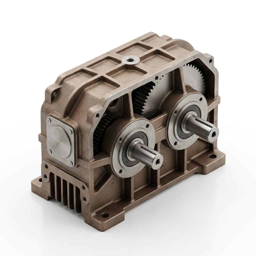
Planetary Gearbox Overhung Load (OHL) Ratings: How to Calculate Bearing Life and Prevent Shaft Deflection
Calculate planetary gearbox overhung load, check ISO 281 bearing life, and compare shaft support options. Use the RFQ checklist to request a supplier review.
A planetary gearbox overhung load (OHL) rating is a permissible external shaft load under stated conditions. To use it, calculate the complete pulley, pinion, or wheel force; identify its application distance; and compare it with the supplier's position-, speed-, and life-dependent limits. Passing the output torque rating alone does not establish adequate bearing life or shaft stiffness.
This guide helps motion control engineers and procurement teams screen precision planetary gearboxes for belt feeders, rack drives, and cantilevered wheels. It provides a reproducible calculation example and an RFQ checklist, rather than product test results.
Quick selection checks
- Confirm the rating point: Some catalogs use the shaft midpoint; others specify a different point or a load-position curve. Never assume a universal reference distance or percentage derating.
- Separate shaft force from bearing load: Internal geometry, preload, and simultaneous axial loads affect the equivalent dynamic bearing load used for life calculations.
- Include belt pretension: Torque determines the tension difference, not the total force on the shaft. A fixed multiplier cannot replace belt tension data.
- Check life and stiffness separately: For ball bearings at unchanged speed, doubling equivalent dynamic load reduces basic rating life to one eighth. That does not predict seal life, backlash, or complete gearbox service life.
Published and last reviewed: November 3, 2026. Scope: Global engineering and procurement screening of precision planetary gearbox output supports in industrial automation. Limits: These are simplified analytical methods. Release a design only against supplier-specific bearing geometry, load limits, lubrication conditions, and a documented duty cycle. Oscillating robot joints and shock-loaded wheels require additional application analysis.
Preparing a drive-axis RFQ? Send the shaft drawing, load position, and duty cycle for an engineering review. Ask the supplier to state which calculations and supporting data are available.
1. Mechanics of Overhung Load: Why Load Position Matters
An overhung radial force acts outside the output bearing support span. Moving a pulley farther from the housing increases bending moment even when transmitted torque is unchanged.
1.1 Shaft Bending and Bearing Reactions
Consider a simplified shaft with two ideal radial supports. Let x be the distance from the shaft shoulder to the load center, c the shoulder-to-front-bearing distance, and a the bearing center span. Dimensions in the diagram are schematic.
For a downward external force Fr, the support reaction magnitudes are:
Front bearing: FB1 = Fr × (a + c + x) / a
Rear bearing:  FB2 = Fr × (c + x) / a
Bending moment at the front support: Mb = Fr × (c + x)
The front reaction acts upward and the rear reaction downward in this ideal model. The front bearing therefore carries more than the external force. Actual planetary carriers may add internal gear forces, bearing moments, and preload; use this model to understand geometry, not to substitute for the supplier's complete bearing analysis.
1.2 Reading a Catalog Radial Load Rating
Record the catalog's load reference point, output speed, required life, force direction, and simultaneous axial or moment limits. For example, SEW's off-center load guidance uses a shaft-midpoint reference for the documented gear units and requires checking both bearing life and shaft strength. Those product-specific constants are not transferable to a precision planetary reducer.
A simplified position correction, only when supplied or approved for the selected unit, can take this form:
Fr,perm(x) = Fr,catalog × c1 / (c2 + x)
c1 = c2 + xref, so the correction equals 1 at the catalog reference xref
Here c1, c2, x, and xref use the same length unit. Never extrapolate an inward load position beyond the supplier's shaft-strength, static-bearing, and combined-load limits. A pulley center at 35 mm cannot be checked directly against a rating defined at 25 mm.
2. Calculating Shaft Loads Across Transmission Types
2.1 Tangential Force from Torque
For output torque T2 in N·m and pitch diameter d0 in mm:
Ft = 2000 × T2 / d0 [N]This is the tangential force transmitting torque. It is not automatically the resultant radial load on the gearbox shaft.
2.2 Transmission Loads: What the RFQ Must Include
Some catalogs use Fr = Ft × fz as a screening convention. Use the selected manufacturer's factor and its stated conditions; there is no universal factor covering all belt pretensions, gear geometries, and shock conditions.
| Transmission type | Force model or required input | Selection consequence |
|---|---|---|
| Timing belt | Tight- and slack-side tensions plus span directions | For nearly parallel spans, shaft force is approximately their sum; torque depends on their difference. Include installation pretension. |
| Roller chain | Both strand forces, sprocket diameter, and dynamic loading | Check chain tension and impact conditions, including polygonal action; use supplier-approved allowances. |
| Spur pinion | Tangential force Ft and separating force Ft × tan(α) | Resultant transverse force is Ft / cos(α) before dynamic allowances. At a 20° pressure angle this is about 1.064 × Ft. |
| Helical pinion | Transverse pressure angle αt, helix angle β, and tooth hand | Separating force is Ft × tan(αt); axial thrust is Ft × tan(β). Evaluate combined force and moment directions. |
| V-belt or ribbed belt | Belt-maker tension calculation and installation setting | Frictional traction can require substantial pretension. Include both working and standstill shaft loads. |
| Flat belt | Both span tensions and their vector directions | Check the full tension resultant and hub position; consider a separately supported pulley shaft when necessary. |
Helical pinion: include axial force and its offset
An axial tooth force at pitch radius r0 can contribute a moment of magnitude Fa × r0. Combine its direction with the radial-load bending moment using the actual tooth contact geometry. Do not simply add scalar maxima or treat a helical gear as a spur gear with a universal multiplier.
3. Bearing Fatigue Life: The ISO 281 Basic Rating Method
3.1 Basic Rating Life in Hours
The SKF rolling-bearing catalog explains the ISO 281 basic rating life method (printed page 89). For constant bearing speed:
L10h = [1,000,000 / (60 × n)] × (C / P)^p
p = 3 for ball bearings; p = 10/3 for roller bearings
L10h is basic rating life in operating hours, n is bearing speed in rpm, C is the bearing's basic dynamic load rating, and P is its equivalent dynamic load. Use the same force unit for C and P.
For applicable radial bearing types, P may be calculated using X × Fr,bearing + Y × Fa,bearing. The bearing maker defines X, Y, load-ratio thresholds, and arrangement rules. Use bearing reactions, including internal loads and preload where relevant, rather than inserting the external shaft force directly.
L10 describes a population fatigue-life rating at 90% reliability. It is not an individual gearbox warranty or the predicted time to leakage. NSK's dynamic-load and fatigue-life chapter explains the statistical basis of bearing rating life.
3.2 Load Sensitivity and Practical Limits
At unchanged speed and dynamic capacity, doubling P leaves a ball bearing with 1/8 = 12.5% of its previous basic rating life. Increasing P by 25% leaves about 51.2%. A roller bearing uses a different exponent.
Basic rating life considers load and speed. Modified life methods also account for reliability requirements, lubrication, and contamination. Temperature changes lubricant viscosity; it does not impose a universal temperature-to-life conversion. Static capacity, minimum bearing load, oscillation, and shock need separate checks.
3.3 Weight Variable Loads by Revolutions
For piecewise-constant operating segments, a constant dynamic capacity, and a load spectrum suitable for the basic fatigue model:
Peq = [Σ(|ni| × ti × Pi^p) / Σ(|ni| × ti)]^(1/p)
nmean = Σ(|ni| × ti) / Σ(ti)
Pi is equivalent dynamic bearing load in segment i, ti is its duration, and |ni| is speed magnitude. For a speed ramp, integrate over the ramp or divide it into representative segments. Reversal does not cancel bearing revolutions.
Time fractions alone work only when segment speeds are equal. Dwell loads consume no rolling revolutions in this model but still require static and lubrication checks. SKF's varying-operating-condition guidance discusses duty intervals, revolution fractions, and the need to retain peak loads (printed page 37).
An external-force equivalent Fr,eq can represent the bearing-life load ratio only if bearing load stays proportional to that force with unchanged geometry and no changing axial, preload, or internal-load contribution.
4. Comparing Output Bearing Arrangements
Bearing architecture helps narrow a shortlist, but frame size or bearing family alone cannot establish radial capacity, efficiency, price, or permissible moment. Request model-specific data.
| Selection question | Deep groove ball bearing support | Opposed tapered roller support | Back-to-back angular contact support | Flanged output assembly |
|---|---|---|---|---|
| Radial load rating | Obtain the complete arrangement rating at the specified load point. | Obtain the arrangement rating and preload assumptions. | Obtain the arrangement rating and contact-angle details. | Obtain force and moment ratings; flange diameter alone is insufficient. |
| Axial loading | Verify limits in each direction and combined-load factors. | Verify opposing bearing load sharing and induced thrust. | Verify pair orientation and axial load sharing. | Confirm the actual internal bearing arrangement. |
| Tilting stiffness | Depends on bearing size, span, clearance, and shaft geometry. | Effective support spread and preload affect stiffness. | Back-to-back spacing and preload affect stiffness. | May shorten the external offset; internal support still determines stiffness. |
| Speed and heat | Check speed, lubrication, and thermal ratings. | Include preload friction and temperature limits. | Confirm preload behavior across operating temperatures. | Use assembly limits for the selected bearing type. |
| Peak or emergency load | Check static bearing load and shaft strength. | Check static capacity and preload retention. | Check static capacity and permissible moment. | Check bearing, flange, pilot, and bolt-joint limits. |
| Cost comparison | Compare quotations for the same duty and target life. | Include lubrication and mounting requirements. | Include preload and assembly requirements. | Include mating hardware and any packaging changes. |
| RFQ evidence | Load-position curve, bearing basis, and shaft drawing. | The same, plus preload and thrust assumptions. | The same, plus pair orientation and contact angle. | Force/moment envelope, interface drawing, and stiffness data. |
A flange conforming to ISO 9409-1 describes an interface; it does not guarantee a cross-roller bearing, zero moment arm, or a stiffness multiplier. Compare the selected assembly's load envelope with the actual application.
5. Shaft Deflection: Check Stiffness Separately from Fatigue Life
5.1 A Transparent Screening Calculation
For an ideal uniform round steel shaft fixed rigidly at the shoulder, with a point force at distance e:
I = π × d^4 / 64
deflection at load point: δ = Fr × e^3 / (3 × E × I)
slope at load point:      θ = Fr × e^2 / (2 × E × I)
Use N and mm throughout, with E in N/mm²; δ is in mm and θ in radians. As an illustration, assume d = 25 mm, e = 35 mm, E = 210,000 N/mm², and Fr = 2,363.6 N. This gives I ≈ 19,174.8 mm⁴, δ ≈ 0.00839 mm, and θ ≈ 0.000360 rad (about 0.0206°).
These are ideal beam results, not measured gearbox deflection. Bearing compliance, shaft steps, keyways, housing movement, and the internal support offset alter actual behavior. Ask the supplier for displacement and tilt at the functional interface under the complete load case; compare those with your mesh alignment, seal, and positioning tolerances.
5.2 Practical Ways to Reduce Deflection
Move the load center toward the bearing support, shorten unnecessary hub overhang, or select a support arrangement with verified stiffness. Where packaging prevents this, evaluate a separately supported driven shaft connected by a suitable coupling, or a rated flange output assembly.
Carrier tilt can disturb gear contact distribution, and shaft movement can challenge seal runout limits. Neither effect has a universal damage angle, contact-stress multiplier, or failure time. Verify the actual gear alignment and seal limits rather than accepting a fatigue-life calculation as proof of positioning accuracy or leak-free service.
6. Worked Example: Screening a Belt-Driven Feeder
This is a hypothetical calculation, not a tested product or customer case. The numbers below demonstrate how load position and revolution weighting change a sourcing decision.
6.1 Declared Inputs
- Motor torque:
3.18 N·m; ratio:10:1; assumed efficiency:0.97; rounded nominal output torque:30.8 N·m. - Peak output torque magnitude:
75.0 N·m; 24-tooth AT10 pulley pitch diameter:76.39 mm. - Shaft usable length:
50 mm; pulley load center:x = 35 mmfrom the shoulder. - Belt spans approximately parallel. Assumed slack-side tensions:
200 Nin acceleration/deceleration and150 Nin cruise. These are example inputs, not belt installation recommendations. - Motion time fractions: acceleration
20%, cruise60%, deceleration20%; mean speed magnitudes:100,200, and100 rpm, respectively. Dwell excluded; target basic bearing rating life:20,000 motion hours. - Hypothetical catalog radial rating:
1,800 Natxref = 25 mm, 160 rpm, and20,000 hours; assumed ball-bearing-fatigue-limited support with proportional bearing/external loads. - Hypothetical supplier-approved correction constants:
c1 = 65 mm,c2 = 40 mm. All other internal loads are neglected for this illustration.
6.2 Step 1: Include Both Belt Tensions
For nearly parallel belt spans, Ft = Ttight − Tslack, so Fr ≈ Ttight + Tslack = Ft + 2 × Tslack:
Peak Ft   = 2000 × 75.0 / 76.39             = 1,963.6 N
Peak Fr   = 1,963.6 + 2 × 200               = 2,363.6 N
Cruise Ft = 2000 × 30.8 / 76.39             =   806.4 N
Cruise Fr =   806.4 + 2 × 150               = 1,106.4 N
The cycle mean speed is 0.2 × 100 + 0.6 × 200 + 0.2 × 100 = 160 rpm. Revolution fractions are therefore 0.125, 0.75, and 0.125, rather than the time fractions:
Fr,eq = [0.125 × 2363.6^3 + 0.75 × 1106.4^3 + 0.125 × 2363.6^3]^(1/3)
      ≈ 1,628.3 N
Using segment mean speeds here assumes a representative constant load within each ramp. If torque or belt tension changes substantially during a ramp, use finer segments.
6.3 Step 2: Apply the Position Correction at Matching Speed
Fr,perm(35) = 1800 × 65 / (40 + 35) = 1,560 NThe equivalent external load is about 4.4% above this illustrative fatigue-limited rating. Under the declared proportional-load assumptions, with the same mean speed and ball-bearing exponent:
Screened L10h = 20,000 × (1560 / 1628.3)^3 ≈ 17,600 motion hoursThis misses the illustrative 20,000-hour target. It is not a prediction that the gearbox will fail at that time. The 2,363.6 N peak must also pass separate static, shaft-strength, and supplier peak-load limits; a lower equivalent load does not waive those checks.
6.4 Step 3: Compare Engineering Changes
Moving the pulley center to x = 15 mm would give a fatigue-based screening capacity of 1800 × 65 / 55 ≈ 2,127 N, and about 44,600 hours under the same simplified model. That peak still exceeds this fatigue-based value; obtain separate peak approval and check shaft strength before accepting the arrangement.
If moving the pulley is impractical, request an alternative bearing support, a separately supported driven shaft, or a larger frame. Recalculate using the new unit's bearing type, rating point, speed, and load envelope. A larger catalog force number alone cannot establish a promised life improvement.
7. Procurement and Engineering RFQ Checklist
- Load position: Drawing with the shoulder datum, load center
x, shaft dimensions, and hub envelope. - Drive element: Belt, chain, pinion, or wheel geometry and pitch diameter; include force directions.
- Tensions and thrust: Belt pretension and working tensions, gear separating force, axial load, or wheel contact loads as applicable.
- Duty spectrum: Segment durations, speeds, torques, reversals, dwell, shock, and emergency-stop conditions.
- Life requirement: Required motion hours, calendar duty, reliability basis, and lubrication assumptions.
- Bearing calculation: Bearing arrangement, reaction/load basis, preload assumptions, and catalog correction method.
- Peak and static limits: Shaft strength, static bearing safety, and combined force/moment acceptance.
- Stiffness requirement: Permissible shaft displacement and tilt at the pulley, pinion, or mounting interface.
- Mounting and environment: Hub fit, torque transmission method, operating temperature, contamination, seal requirements, and lubrication plan.
- Supplier deliverables: Model drawing, stated rating conditions, calculation assumptions, and any available application-specific validation records.
Use the Gearbox Sizing and Service Factor Calculator for the torque side of your RFQ; it does not calculate OHL or bearing life. The Interchange Matrix can help shortlist replacement candidates, but dimensional similarity does not establish equal radial-load capacity.
8. Frequently Asked Questions
Can an external pillow block support the shaft end?
It can, but a third support changes load sharing and can introduce alignment loads. A self-aligning bearing does not automatically solve all overconstraint or thermal-expansion issues. Have the complete support system analyzed; a separately supported driven shaft with an appropriate coupling may simplify alignment.
Is permissible radial force the same as emergency radial force?
No. A permissible operating rating may be governed by fatigue, shaft strength, or another limit under stated conditions. Symbols such as Fr,max are not consistent across manufacturers. Ask for the definition and duration of each operating, static, and emergency limit; do not interpret a catalog maximum as a structural yield threshold.
Do helical pinions always create more radial force than spur pinions?
Not necessarily for the same tangential force and specified transverse pressure angle. Helical teeth also generate axial thrust, so the complete bearing force and moment combination matters. Use the actual geometry and tooth hand rather than a blanket transmission factor.
Does high temperature always reduce life by a fixed factor?
No. Evaluate lubricant viscosity at operating temperature, contamination, bearing material limits, and preload changes. The ISO 281 basic life equation does not itself calculate those effects; use an appropriate modified-life method and thermal review.
Is a smooth shaft always better than a keyed shaft?
A keyway can concentrate bending stress, but the complete joint design governs the choice. Verify shaft fatigue, hub fit, clamping capacity, and assembly requirements. Neither a keyless clamp nor a keyed joint increases the gearbox bearing's published capacity.
Does an ISO 9409-1 flange guarantee high moment capacity?
No. It specifies interface geometry. Obtain the selected output assembly's permissible forces, tilting moment, stiffness, and bolt-joint requirements. The attached pinion or plate still has a real load offset.
What evidence should procurement request for the load rating?
Request the rating method, reference distance, speed/life basis, bearing and shaft assumptions, and any available load-test conditions and acceptance criteria. Do not assume every gearbox has undergone a full application-life test. Calculation evidence and physical endurance-test results are different deliverables.
Will a bearing with L10h of 15,000 hours fail at 15,001 hours?
No. Basic rating life is a statistical fatigue rating, not a scheduled failure time. Individual lives vary, and contamination, mounting, lubrication, seals, or positioning requirements can limit service earlier. Do not infer a universal median-life multiplier or maintenance interval from L10h alone.
9. Next Steps for a Defensible Selection
Select a planetary gearbox by checking torque, complete shaft loads, actual load position, bearing fatigue life, peak capacity, and stiffness together. Keep the catalog conditions beside the calculation so a buyer can distinguish a supported model recommendation from an unverified frame-size substitution.
Contact Robotized Gearbox with your shaft drawing and duty-cycle table to discuss a candidate gearbox and the load-rating evidence needed for your RFQ.
Sources / References
These primary manufacturer references support the methods indicated below. They do not certify the hypothetical example or any Robotized Gearbox product. Source review: November 3, 2026.
- SKF — Rolling bearings, catalog 17000/1 EN, printed page 89, basic and modified rating life: SKF rolling-bearing catalog (PDF). Supports the ISO 281 equation, exponents, reliability basis, and lubrication/contamination limits.
- SKF — Bearing rating life, printed page 37, varying operating conditions: SKF duty-interval guidance (PDF). Supports representative load blocks, revolution fractions, and independent checks on peaks; its application context is screw compressors.
- SEW-EURODRIVE — Output side: Overhung load conversion for off-center force application: SEW load-position guidance. Supports checking the documented rating point and both bearing-life and shaft-strength limits. Its constants apply to the documented SEW gear units, not planetary gearboxes generally.
- NSK Americas — Chapter 5: Dynamic Load Ratings and Fatigue Life: NSK bearing-life fundamentals. Supports the statistical meaning of dynamic load ratings and fatigue life.
Author

Categories
More Posts
Preventing Thermal Failure in AGV and AMR Drive Gearboxes: A Sourcing Guide
Why compact AGV wheel gearboxes fail from heat before they fail from load, and how procurement and engineering teams can specify thermal limits correctly.
Specifying Gearboxes for High-Payload Cobots: Why 20kg+ Arms Require Cycloidal Drives
Learn how to specify high-payload cobot gearboxes for 20kg+ arms: harmonic vs cycloidal tradeoffs, joint architecture, RFQ checks, and supplier evidence.
Nabtesco RV Gearbox Replacement: How to Verify Drop-In Compatibility from Chinese Suppliers
A procurement guide for sourcing RV-style cycloidal reducers from China. Learn how to verify drop-in compatibility, stiffness, and shock load capacity before switching.